Nope. If anything, parallel 5+10 and 6+12, i.e. the two existing channels... resistors probably required (0.22 ohms or so?).
Pair of 8 Ohms is same-as 4 Ohms. Connect this like the left (stock) diagram. You won't get significant more power with the right diagram.
0.22R ballast resistors might turn out to be a bit on the low side. There's a worst case DC offset of 100mV and a worst case gain mis-match of 1dB for this chip.
Pair of 8 Ohms is same-as 4 Ohms. Connect this like the left (stock) diagram. You won't get significant more power with the right diagram.
Mm... I a bit confused about this. If I have 12V going into an 8 ohm load that'll draw 1.5A and result in 18W of power. Yes?
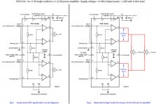
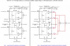
So in the standard configuration (2x22W), each driver will be drawing 1.5A and putting out 18W of power. But if I bridge the way I have shown in my right diagram won't this increase the capability to 44W and if I then connect both 8 ohm drivers in parallel (ergo 4 ohm impedance), each drawing 1.5A meaning 3A current won't that result in 36W of power?
Or have I completely misunderstood the whole Ohms Law principal? And what's the point of connecting speakers in parallel if not to get an increase in power?
Help!
> If I have 12V going into an 8 ohm load that'll draw 1.5A and result in 18W of power. Yes?
For a DC load, 8r directly on a 12V supply, yes.
But this is an *audio* amplifier. And for historical reasons we test with Sine Wave.
This explanation would be simpler with a simple (not bridged) amplifier. For 12V supply we bias to 6V (with cap to block the DC from the speaker) and swing to zero and 12V. So 12V peak to peak. Since we test with sine wave, the RMS of a sine is P-P/2.828. 4.2V RMS. 4.2Vrms in 8 Ohms is 2.2 Watts.
This is a Bridged amplifier. We still bias each side to 6V DC and one swings to zero and 12V; but the other swings to 12V and zero. So now we have 24V peak to peak, 8.4V RMS. In 8 Ohms this is 8.8 Watts; in 4 Ohms this is 17.6 Watts.
Note that the two halves of each channel work in *anti-phase*. One goes up, the other goes down, and vice versa. Your plan connects two antiphase outputs together and they will fight violently. To get them in-phase you would connect 6 to 12, 8 to 10.
However doing this does NOT change the voltage to the load. Still 24V peak to peak. It conceptually doubles the *available current*. However I is still V/R and same voltage same load you get same current. The doubled current capacity is not used. You would have to find a 2 Ohm load to get all the power.
Connecting two power outputs together always risks a "fight". You are correct that some dummy resistance between them helps limit the fight. ANY difference of voltage between the two outputs will cause useless cross-current. Such a voltage difference may be DC offset or difference of AC gain. On the high-quality LM3886 paralleled amp rigs we often resort to 1% resistors and DC servos. The car-audio chips don't make all the gain and offset trim points available. While we could probably contrive a way, this spoils the simplicity of common car-audio chips.
Attachments
Thank you. I really appreciate the detailed reply. There are a couple of points I don't fully understand, but I think I get the gist of what you are saying.
Basically I'm trying to get the best out of two 8 ohm Jenson MOD5-30 drivers with a 12VDC supply for a busking amp. Seems little point using them if I'm only going to get 8.8W to each when they're rated to 30W.
I was hoping that by playing around with an IC and using the speakers in parallel I might be able to get more oomph!
Dunno which way to go forward now.
> get the best out of two 8 ohm Jenson MOD5-30 drivers with a 12VDC supply
Sell them and get two Mod 8-20 4Ohm, one per channel.
Bigger cone area makes the most of limited power. Nominally 2dB more for the Eight over the Five, but 5dB more 100-200Hz where the guitar has "body". This alone is like having 2X to 3X the electrical power (and battery weight).
And the 4 Ohm model (not available in the Five) is a best-fit for auto-sound power amps.
> I'm only going to get 8.8W to each when they're rated to 30W.
30 Watts in a Five, for instrument use, has to be about low efficiency (less air-action per electrical Watt). Otherwise a Five with a full-range (even guitar) signal would just slap itself silly. The Five is for a bedroom amp where you do NOT want maximum acoustic output.
Seems little point using them if I'm only going to get 8.8W to each when they're rated to 30W.
Its not as bad as it looks.
To get twice as loud needs 10x power.
So to be twice as loud a 8 watts needs 80 watts.
- Status
- Not open for further replies.
- Home
- Amplifiers
- Chip Amps
- Can you do this with a TDA1554?