This thread explores the use of adaptive filtering/beamforming techniques to get better resolution quasi-anechoic speaker measurements.
Some of the initial ideas about using such techniques is motivated by the work done around here: https://www.diyaudio.com/community/...d-scanner-on-a-shoestring.318151/post-7038419 by @aslepekis and @Kravchenko_Audio
In this thread, I intend to explore more along similar lines and use more beamforming algorithms to see if something works out. Atleast we'll get to know some of the limitations of such techniques.. 🙂
@fluid has been helping me with some initial ideas, papers, and motivation to pursue this kind of exploratory work.. 🙂
In below posts I intend to update the results of experiments (and eventually the Matlab code I have been writing to do all this)

The below paper might give some introductory information about the kind of beamforming techniques that we initially plan to test out namely
1) Delay Sum Beamformer
2) MVDR beamformer
3) GSC beamformer
https://arxiv.org/pdf/1212.6080.pdf
1) Delay Sum Beamformer
2) MVDR beamformer
3) GSC beamformer
https://arxiv.org/pdf/1212.6080.pdf
Just to start playing around with real data and to try and understand how to implement different types of beamforming, I took measurements of a speaker (QAacoustics 2020i) at 10cm distance increments on-axis (with the tweeter) starting from 100cm and ending at 160cm, resulting in a total of 7 measurements. This was done in a room where the closest boundary was the floor which was about 125ish cm down from tweeter height (this is probably better done outdoors where the single reflection from the floor is the only issue)
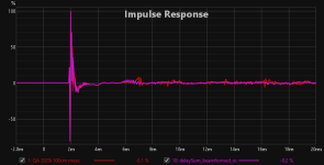
Here is how the impulse responses look like:
100cm

110cm

120cm

and so on..
After doing Align SPL, estimated IR delay-based compensation, resulting impulse response overlay is given below

As seen in the above pics, the first reflections occur in the 4ms to 5ms region. As the distance of mic increased, the reflections started to come in closer towards 4ms, as expected.
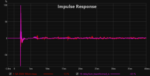
For trying out delay-sum beamforming, I did vector averaging of above responses giving the following impulse response

As per expectations, now the overall SNR seems to have improved with diminished amplitude for the reflections everywhere most evident in the 4ms - 5ms region.
Here is a comparison of the frequency responses corresponding to 100cm, 110cm and 120cm distances and the vector average/Delay-Sum beamforming (All ungated but 1/24 octave smoothed).

Here is how the impulse responses look like:
100cm
110cm
120cm
and so on..
After doing Align SPL, estimated IR delay-based compensation, resulting impulse response overlay is given below
As seen in the above pics, the first reflections occur in the 4ms to 5ms region. As the distance of mic increased, the reflections started to come in closer towards 4ms, as expected.
For trying out delay-sum beamforming, I did vector averaging of above responses giving the following impulse response
As per expectations, now the overall SNR seems to have improved with diminished amplitude for the reflections everywhere most evident in the 4ms - 5ms region.
Here is a comparison of the frequency responses corresponding to 100cm, 110cm and 120cm distances and the vector average/Delay-Sum beamforming (All ungated but 1/24 octave smoothed).
Last edited by a moderator:
I have so far tried out writing Matlab code for delay-Sum beamforming and MVDR beamforming.
The MVDR beamformer is a data-adaptive beamformer whose performance depends on the training data given to it for estimating the beamformer weight vector.
My initial experiments use the above mentioned 7 measurements and the resulting "Mic array" in an endfire array configuration.
For MVDR beamformer training, I just used the data from the tails of the above impulse responses. This is in no way an optimal method and the results may also reflect that suboptimality.
Since I don't have access tp high resolution anechoic data for this speaker, I am comparing against my own quasi-anechoic measurement of the speaker for the time being.
Here is a comparison between the quasi-anechoic measurement, MVDR beamformer output and delay sum beamformer output

Note that the array configuration I have is also not the optimal one and probably once I have about more measurements of the speaker, the averaging might kick-in and smooth out the variations better (Just as a visual aid, I am using that 1/12th smoothing for now on the beamformed data. It will be removed later on).
PS: Ignore the absolute SPL levels which has something to do with impulse response import into REW. We will focus on getting it right later on
The MVDR beamformer is a data-adaptive beamformer whose performance depends on the training data given to it for estimating the beamformer weight vector.
My initial experiments use the above mentioned 7 measurements and the resulting "Mic array" in an endfire array configuration.
For MVDR beamformer training, I just used the data from the tails of the above impulse responses. This is in no way an optimal method and the results may also reflect that suboptimality.
Since I don't have access tp high resolution anechoic data for this speaker, I am comparing against my own quasi-anechoic measurement of the speaker for the time being.
Here is a comparison between the quasi-anechoic measurement, MVDR beamformer output and delay sum beamformer output
Note that the array configuration I have is also not the optimal one and probably once I have about more measurements of the speaker, the averaging might kick-in and smooth out the variations better (Just as a visual aid, I am using that 1/12th smoothing for now on the beamformed data. It will be removed later on).
PS: Ignore the absolute SPL levels which has something to do with impulse response import into REW. We will focus on getting it right later on
Here is a comparison of the above measurements with a just 1/12 octave smoothed in room measurement of the speaker from 100cm away

To understand the effect of the beamforming and reflection suppression, here is an impulse response overlay for the original in room measurement from 100cm away and the beamformer output
In room measurment as it is vs Delay-Sum beamformer output

In room measurment as it is vs MVDR beamformer output

To understand the effect of the beamforming and reflection suppression, here is an impulse response overlay for the original in room measurement from 100cm away and the beamformer output
In room measurment as it is vs Delay-Sum beamformer output
In room measurment as it is vs MVDR beamformer output
Attachments
To understand what the beamformers are doing, let us study their polar patterns.
Here is how the Delay-Sum beamformer for this configuration is focussing during signal reception

We have a spike around 0 degrees (on axis with the speaker) and a lot of nulls and spikes as angle increases in the horizontal plane. Ideally we would have liked to have a single spike around 0 degrees and heavy attenuation everywhere else.
Here is how the MVDR beamformer for this configuration is focussing during signal reception

As of now, with this basic experiment, we dont have much difference between the polar patterns of the two beamformers. The nulls are not well focussed towards directions from where reflections are coming from.. It is just randomly spread out as of now.
In coming days, let us try to understand if this can be optimized in horizontal and vertical dimensions by creating different array configurations and using different algorithms.. 🙂
Here is how the Delay-Sum beamformer for this configuration is focussing during signal reception
We have a spike around 0 degrees (on axis with the speaker) and a lot of nulls and spikes as angle increases in the horizontal plane. Ideally we would have liked to have a single spike around 0 degrees and heavy attenuation everywhere else.
Here is how the MVDR beamformer for this configuration is focussing during signal reception
As of now, with this basic experiment, we dont have much difference between the polar patterns of the two beamformers. The nulls are not well focussed towards directions from where reflections are coming from.. It is just randomly spread out as of now.
In coming days, let us try to understand if this can be optimized in horizontal and vertical dimensions by creating different array configurations and using different algorithms.. 🙂
There seems to be an issue with the images in the post 3. They all just show as [string of numbers].png with a forum error message returned when trying to open in a new tab.
Anyway, I'm interested, based on positive experiences with conference room beamforming mics. I'll have to learn up on the types of beamforming.
Anyway, I'm interested, based on positive experiences with conference room beamforming mics. I'll have to learn up on the types of beamforming.
That was what intrigued me about the idea, is there a way to significantly reduce the earliest reflections without introducing any other errors. Looking forward to see what comes out 😀In coming days, let us try to understand if this can be optimized in horizontal and vertical dimensions by creating different array configurations and using different algorithms.. 🙂
Thoughts: aim the microphone away from the speaker at various angles and distances, and make measurements side to side rather than simply at varying distance. Perhaps this will lead to better distinction of the various sound sources (reflections) e.g. https://patents.google.com/patent/US8923529B2/en?oq=965957
Geeks got to geek-out, man 🙂 Probably should ping @wesayso too. Following.

PSST: This is why there are still corner speakers and 90x40 degree horns running analog and passive 🙂
PSST: This is why there are still corner speakers and 90x40 degree horns running analog and passive 🙂
Best using the cross-correlation alignment feature rather than Estimate IR delay before the vector average.
One of the tricky parts with any array, is more the practicality of it.That was what intrigued me about the idea, is there a way to significantly reduce the earliest reflections without introducing any other errors. Looking forward to see what comes out 😀
So find a way to do this easy and consistently.
But, I agree, it's interesting to discover other ways! 👍
Differential beamforming, used in hearing aid kind of applications with closely spaced array elements (mics) looks like a promising candidate for our purpose until.......... (Let's look at that aspect in the end).
I think, probably, someone has already tried out this beamforming method.
The good part of the algorithm is that the algorithms are already implemented and available in Matlab.
Very nice polar patterns can be designed with few mics:
This link shows more details and how to use it in Matlab
https://in.mathworks.com/help/phased/ug/introduction-to-differential-beamforming.html
With such algorithms, the directivity pattern can remain invariant over relatively wide frequency ranges compared to regular beamforming with fixed spacing of array elements. and with an N-element array, N-1 nulls can be placed at desired angles. Again examples are available in above link.
Here is a 6 element array and its polar pattern over a frequency range that we are all interested in

The array elements are spaced 3cm apart (or the same mic moved in 3cm steps each time).
Here I specified the nulls to form at 0 degrees (broadside direction), 30 degrees, -30 degrees and 90 degrees.

Now the bad part.. 😀
The SNR (gain over white noise) significantly reduces as the number of elements increases
Here is it for the above configuration. SNR is very bad at low frequencies

But I think even a 2-element array is worth trying out to eliminate single reflections like floor, ceiling etc..
Anyway, I will try this method out when I get some time.. 🙂
I think, probably, someone has already tried out this beamforming method.
The good part of the algorithm is that the algorithms are already implemented and available in Matlab.
Very nice polar patterns can be designed with few mics:
This link shows more details and how to use it in Matlab
https://in.mathworks.com/help/phased/ug/introduction-to-differential-beamforming.html
With such algorithms, the directivity pattern can remain invariant over relatively wide frequency ranges compared to regular beamforming with fixed spacing of array elements. and with an N-element array, N-1 nulls can be placed at desired angles. Again examples are available in above link.
Here is a 6 element array and its polar pattern over a frequency range that we are all interested in
The array elements are spaced 3cm apart (or the same mic moved in 3cm steps each time).
Here I specified the nulls to form at 0 degrees (broadside direction), 30 degrees, -30 degrees and 90 degrees.
Now the bad part.. 😀
The SNR (gain over white noise) significantly reduces as the number of elements increases
Here is it for the above configuration. SNR is very bad at low frequencies
But I think even a 2-element array is worth trying out to eliminate single reflections like floor, ceiling etc..
Anyway, I will try this method out when I get some time.. 🙂
This kind of technique has already been explored here 😀
https://www.diyaudio.com/community/...ons-measurement-in-matlab.388032/post-7168757
https://www.diyaudio.com/community/...ons-measurement-in-matlab.388032/post-7168757
Thank you very much @vineethkumar01 for digging into this! I'm following this thread with interest.
Optimizing the array to address specific reflection angles is an excellent idea, and the idea that even a two element array could provide reduction of particular reflections is exciting. I can anecdotally confirm that a two element array can do that; a cardioid mic with the null pointed at the ground nearly eliminates the the only reflection outside. Using a two element array with omni's would then improve the response of what is captured from the speaker.
I'll also add that some optimization can be had by changing the speaker/mic distance to a reflective surface for each "data point" (array element?). For example, keeping the speaker and microphone positions relative to each other the same between two measurement points, but insuring that the reflection in one measurement arrives at X milliseconds and (X milliseconds)/2 in the other can do a pretty good job at smoothing the effects of a reflection.
So what does a poor independent consultant do when he doesn't have Matlab? Will Octave run these wonderful simulations? Speaking as a guy that really is not adept at using Octave either!
It's "only" 900 bucks a year or $2250 for just a one-time license, lol
Well unless you need more fancy things, in that case it's "only" 4k a year.
Personal home license is 120 bucks one time purchase.
https://mathworks.com/pricing-licensing.html
Well unless you need more fancy things, in that case it's "only" 4k a year.
Personal home license is 120 bucks one time purchase.
https://mathworks.com/pricing-licensing.html
@Kravchenko_Audio: For us in India, the Matlab home edition purchase price is USD 69 + USD 63 total (for Signal processing toolbox + DSP System Toolbox + Phased array toolbox).
I am using Matlab for quick study and experiments since it has built-in toolboxes for most of the signal processing we need (also because I have been using it since 2008 and am more familiar with it).
If some algorithm works out/is interesting, we can implement it from scratch in some other open-source software like Octave.
Old dog I am. I finished school in 1987.
Not always easy to get into software that will not get used much. And take longer to learn than I can justify.
But I appreciate the opportunity to learn. If this turns out to offer a real benefit then time will be spent into it to learn more.
Not always easy to get into software that will not get used much. And take longer to learn than I can justify.
But I appreciate the opportunity to learn. If this turns out to offer a real benefit then time will be spent into it to learn more.
- Home
- Design & Build
- Software Tools
- Can we improve resolution of quasi-anechoic speaker measurements using adaptive filtering techniques: A study