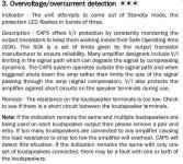
I have an Azur 640A V2 that's going into the "three flashing lights" protection mode after about 15 minutes of use. (I've attached the relevant snippet about what three lights indicates below.) It does this hooked up to 8 ohm speakers and being fed music, as well as with an 8 ohm dummy load and fed a 1kHz sine wave.
From what I've observed so far, it appears to be a temperature-related fault. It doesn't happen right after power on. Once it does go into protection, unplugging and plugging in the amp resets it, but then it more or less immediately trips again, even without a load connected and no signal being input.
I know there are a number of diyaudio members who have (or had) this amp, and so I wanted to see if anyone has encountered this particular fault before I dive in to begin troubleshooting in earnest.
Attachments
........a friend gave me his 640 A amp . with a few flaws i found out.
first there was a literally broken ne5532 behind the rec-pb inputs (5532 had a rent through it)........have a look at this.
second the 7815 voltage regulator was burnt through.....you can measure
the voltage at the regs'.........
and third the input selector opamp ( pcb bottom side) was damaged and the (100 ohms) res connected to it (on the pcb top side).......
Hmm, sounds like the bias might be going into thermal runaway, although there are other possibilities. A cold-spray is sometimes useful for tracking down thermal issues.
I'd start by measuring/monitoring the bias and see if that's rising uncontrolled as the unit
warms up.
I'd start by measuring/monitoring the bias and see if that's rising uncontrolled as the unit
warms up.
........a friend gave me his 640 A amp . with a few flaws i found out.
first there was a literally broken ne5532 behind the rec-pb inputs (5532 had a rent through it)........have a look at this.
second the 7815 voltage regulator was burnt through.....you can measure
the voltage at the regs'.........
and third the input selector opamp ( pcb bottom side) was damaged and the (100 ohms) res connected to it (on the pcb top side).......
Thanks. I'll check out the 7815.
Hmm, sounds like the bias might be going into thermal runaway, although there are other possibilities. A cold-spray is sometimes useful for tracking down thermal issues.
I'd start by measuring/monitoring the bias and see if that's rising uncontrolled as the unit
warms up.
I just watched the bias on cold power up and then right before it shut down for three of the output transistors. (I could only check the fourth after the first shut down--not enough meters!) It started out around 14mV, dropped to approximately 13.5mV, and then was a little over 14mV at shut down. When I power on again, I have about 20 seconds to measure before it shuts off again, at which point the outputs are each at close to 15mV.
Ok, I checked the bias again, this time for all four outputs simultaneously. Bottom line: I don't think thermal runaway is the issue. The spec in the service manual is for a bias of 13mV, and each output is pretty close to this when the unit shuts down.
I'm figuring the next step is to take a closer look at the portion of the protection circuit that applies to this fault. One issue is that the schematic I have (from HiFiEngine) doesn't quite match up with what's in front of me. If anyone out there has a different one available, let me know.
I'm figuring the next step is to take a closer look at the portion of the protection circuit that applies to this fault. One issue is that the schematic I have (from HiFiEngine) doesn't quite match up with what's in front of me. If anyone out there has a different one available, let me know.
If all is lost-
Cambridge Audio Repair London - Get Azur 640A V2 Amplifier fixed by Electronic Partners
Seems its a common fault.
Cambridge Audio Repair London - Get Azur 640A V2 Amplifier fixed by Electronic Partners
Seems its a common fault.
I would be looking for caps on the protection circuit. If there is a IC like the upcxxx series, check the datasheet for pin voltages & compare. You say 15mV BIAS.
Do You mean DC at the speaker output ?
Do You mean DC at the speaker output ?
Ok, I sorted out the problem. The two protection boards are mounted vertically, with a piece of foam sandwiched between them (to stabilize, I assume). Apparently, the adhesive tape used to hold the foam against the solder side of the boards had become conductive, causing an erroneous fault reading. After removing the foam and all traces of the adhesive, the amp no longer goes into protection.
That's plausible, knowing the many faults Audio Partnership had/has with their Chinese assembled products. Who in their right mind though, would fit foam packing or use adhesive tape on or near to the copper side of a PCB fitted in a consumer power amplifier anyway?
The Cambridge Audio line isn't renowned for parts or build quality but this is just unprofessional, regardless of any technical whitewashing about modern glues and foam that would likely say otherwise.
I'd be interested to know how you found out about the glue problem. Was it another thread/ forum suggestion?
It was just a hunch. I was trying to eliminate any possible stray conductive pathways, and had already finished cleaning off all the excess glue around the capacitors in the amp board. When I noticed the foam between the protection boards, I thought, "Seriously? This is not good."
I worked at Cambridge Audio (Audio Partnership) for over a year as a junior electronic engineer.
I built a 651A out of bits kicking around the lab. the only issue I had with it was similar to OPs. The thermistor is screwed onto the heatsinks for the output stages. The slight differential movement between the heatsink and PCB made the thermistor solder connections crack and go dry. Just try reflowing the solder here - it might fix it.
I built a 651A out of bits kicking around the lab. the only issue I had with it was similar to OPs. The thermistor is screwed onto the heatsinks for the output stages. The slight differential movement between the heatsink and PCB made the thermistor solder connections crack and go dry. Just try reflowing the solder here - it might fix it.
- Home
- Amplifiers
- Solid State
- Cambridge Audio Azur 640A V2: Shutting down with three flashing lights