How would one go about calibrating a frequency response measuring setup (I’m using UMIK-1 and REW) to measure drivers so as to generate SPL vs frequency curves like on driver datasheets? What I would like to do is measure drivers I have to compare with the factory curves. I have a pretty good setup and have gotten excellent correlation in terms of the shape of the curve (specific peaks and valleys in the response), but my SPL level is off.
I have some new RS150P mids on hand and at 500Hz, the SPL is stated as 90dBSPL on the factory curve. I’m considering just adjusting the output of the amp so that my readings end up with that value and keeping that amp as a dedicated amp for driver measurements. Not “precise,” but good enough for hobby work?
I have some new RS150P mids on hand and at 500Hz, the SPL is stated as 90dBSPL on the factory curve. I’m considering just adjusting the output of the amp so that my readings end up with that value and keeping that amp as a dedicated amp for driver measurements. Not “precise,” but good enough for hobby work?
Start with a calibrated microphone. Inconsistencies will show up on all measurements but are not always easy to spot. Next, research a standard measurement baffle and create a reflection free environment.
You'll need to do more if you are also going for measuring the absolute level.
You'll need to do more if you are also going for measuring the absolute level.
If it's just the SPL, get an SPL meter and set the SPL level with that.
I'm unsure why the SPL matters, unless you're measuring the speaker efficiency. From what I've seen, the FR curve simply moves wholly up and down with how loud you're playing the test sound. Unless -
- you're driving the level hard enough to exacerbate edge diffraction and other non linear effects.
- you're driving the level hard enough so the driver itself is strained beyond what it'd ever be in your normal listening situation.
I prefer pink noise testing for a quick look, and understand that swept sine will bring into focus response anomalies in a better way. If you're looking for trouble, pure sine is the way to go.
Music has many frequencies happening simultaneously, as does pink noise. Music can also have quite dominant pure tones in certain parts, which sine wave testing better represents.
Since you are using the Umik-1 you should already have the SPL calibration built in, right? Does REW pick up absolute SPL from the Umik-1 calibration file?
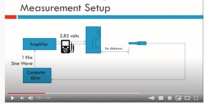
For the amp, find output level settings for REW, your source and your power amp that give you an output voltage of 2.83 volts at the speaker terminals. That way you have level that is applicable to all your drivers. For many drivers that will be loud.
Published speaker driver measurements traditionally state the SPL at 1 watt and 1 meter distance. Obviously a 4 ohm, 6 ohm, 8 ohm and 16 ohm speaker will need different voltages for that 1 watt. Sticking to 2.83V give you a better idea of how the drivers will play against each other.
I found this on youtube which appears to answer my question. I was thrown off by the fact that the voltage measurement needed to be ac, but the signal is ac, so I think I'm good with this. Intuitively, I find it hard to be believe I'm going to be able to get to 90 SPL for a tweeter, seems awfully loud. And when I do the sweep, I am going to need to put a capacitor in line, what is the typical value for this?
Attachments
A normal tweeter won't die from 2,83V full range signal. But if you're afraid of damage, adjust the source signal so that it only contains signals from 250Hz upwards. If you are to use a cap, pick a 47µF.
Btw, make sure your meter is true RMS at high frequencies. A lot of cheap voltmeters only do RMS under 100Hz. You would ruin your tweeter if you put a lot more on it than 2,83V, believing the false readout of your meter.
Btw, make sure your meter is true RMS at high frequencies. A lot of cheap voltmeters only do RMS under 100Hz. You would ruin your tweeter if you put a lot more on it than 2,83V, believing the false readout of your meter.
True, but you don't have to measure the amplifier voltage at 1000 Hz or higher. You can measure anywhere from 50-150 Hz and the higher frequencies will be the same voltage if you amp is linear. It is highly likely to be linear.
Ditto what Markbakk says. Start your tweeter sweep high like 250 Hz or higher.
Ditto what Markbakk says. Start your tweeter sweep high like 250 Hz or higher.
Had to order myself a meter that reads true rms. Let's hope it is true that it reads true rms. I remember these to have been very expensive at one point, but can now be purchased for $20! What would be a good way to confirm it reads true vs. not? They are for power measurement, so probably not high frequency, does not even state what frequency on the specs.
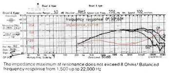
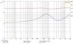
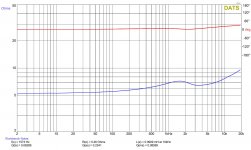
First up on my projects for this setup is to evaluate the improvement of changing the ferro fluid on a D28AF. I have posted the factory response curve, a curve from DATS on a good unit, and the curve for the candidate for fluid replacement. Plan on doing before and after, with hopefully the after curve showing good correspondence with the good unit, which is measuring well compared to factory.
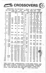
Based on the factory curve, at 250Hz, impedance is 6 ohm, so I guess that is where the 47uf or so capacitor is indicated? I'm looking at the table posted. Don't understand, though, why there are 6dB and 12dB columns. Is the 6dB column the appropriate one since I am just putting a single cap in line?
First up on my projects for this setup is to evaluate the improvement of changing the ferro fluid on a D28AF. I have posted the factory response curve, a curve from DATS on a good unit, and the curve for the candidate for fluid replacement. Plan on doing before and after, with hopefully the after curve showing good correspondence with the good unit, which is measuring well compared to factory.
Based on the factory curve, at 250Hz, impedance is 6 ohm, so I guess that is where the 47uf or so capacitor is indicated? I'm looking at the table posted. Don't understand, though, why there are 6dB and 12dB columns. Is the 6dB column the appropriate one since I am just putting a single cap in line?
Attachments
If you measure sine waves, then the true RMS isn't really a problem. If you want to measure music or noise then RMS is of more use. But REW will set the noise levels for you relative to sine anyway.
This will help you calculate a protection cap for your tweeter sweeps.
2-Way Crossover Calculator / Designer
2-Way Crossover Calculator / Designer
What are you looking for and why?
If, as you claim, the FR is parallel the imaginative picture the marketing department of your speaker manufacturer posted, all you need is to test output at a single frequency to learn sensitivity/efficiency. Rare for absolute values to matter in the least unless you have one of those clunky old passive crossovers which is missing an L-pad. You want to build a system and have built-in the means to tune it, not pray that the miracles of engineering math will result in a perfect psycho-acoustic system if done precisely.
Given all the loosey-goosey links between the start and finish, you need to work in acoustics, not electricity. So an AC voltmeter isn't needed but an SPL meter is - possibly a free one for your smartphone will do OK, if designed for that model.
B.
Last edited:
- Home
- Loudspeakers
- Multi-Way
- Calibrating DIY Frequency Response Measurements