Sure this should be very simple and easy but not something I've paid a great deal of attention to before as... well there simply wasn't any need.
Anyway, now working on a new 3-way and it's becoming an issue, as power handling of the woofer is 200 watts, midrange is 50 watts, tweeter is 100 watts... so I can't help but feel that the midrange's power handling is going to be under, which is a real shame as in a WMT configuration they play very nicely together.
How do I calculate the power division from the audio signal? I would have thought this was very easy but it seems slightly difficult to find a turn key formula...
For what it's worth, I'm currently planning on crossing the mid with the tweeter using a 2nd order acoustic/electric filter between 3 and 4KHz
I haven't made a decision regarding bass to mid, but wouldn't want to go higher than 400Hz
I think it is kind of complicated because the XO's are reactive loads. Furthermore, the XO and drivers once in a speaker, the reactive load changes due to the impedance curve the cabinet alignment imposes on the drivers and XO. The power is a function of frequency and can vary dramatically over the frequency range. The best way is to simulate the speaker and XO and the cabinet and you can easily calculate the power of any particular driver or the total power. I do this in AkAbak all the time.
So do I need to get to simulation stage before I can gain a reliable plan? I was hoping there could be a formula I could apply with approximate transfer functions... so all I need is a formula for total percentage of power transferred in terms of frequency then basic calculus will do the rest...
Even without speaker box impedance, it is still a reactive (freq dependent) system. There are probably closed-form solution formulas for calculating power in such XO networks, I don't know how to do it with pencil and paper so use sims. You can use a spice based program to do the analysis easy enough. Texas Instruments has a very nice graphical Spice program called TINA you can download.
If I understand you correctly, the table on this page BiAmp (Bi-Amplification - Not Quite Magic, But Close) - Part 1 is the one you want. This shows that at 350Hz, the power split is 50:50. That is audio power. You don't say what the efficiencies of the drivers are, so unless they are equal, it's meaningless.
What is your SPL target? Can you reach that within the 50W rating of the driver? If you can, you have no worries, just don't try to exceed your target SPL.
Brian
What is your SPL target? Can you reach that within the 50W rating of the driver? If you can, you have no worries, just don't try to exceed your target SPL.
Brian
As an example of how the power can be calculated using a sim in Akabak, here is Zaph's ZRT speaker (zaph|audio - zrt - revelator tower) XO:

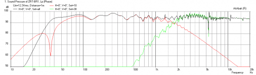
Here is the sim of the response in a slightly modified bass reflex I was working on for another member (includes reflections for floor bounce, rear wall, and diffraction effects):

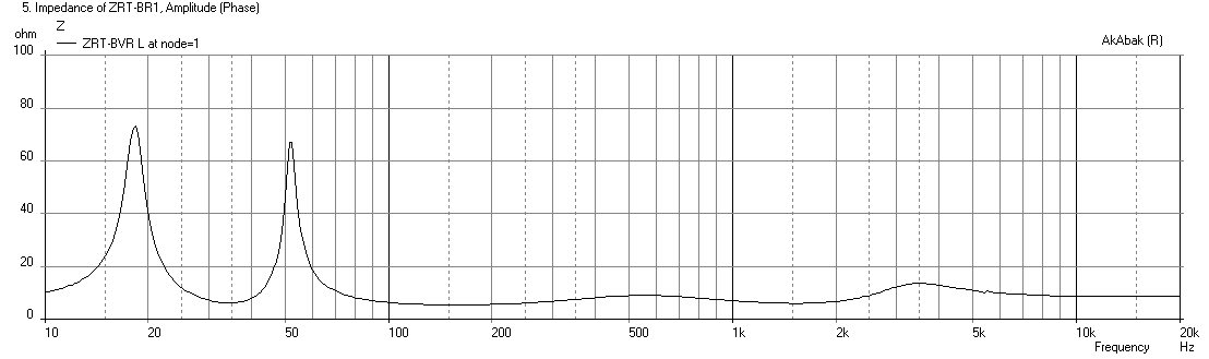
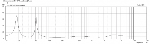
Here is the predicted impedance:
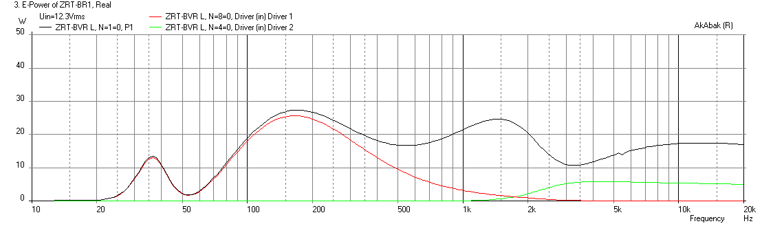
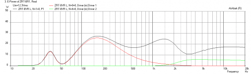
Here is the predicted electrical power input (for 12.3 volts corresponding to 6.5mm xmax on the woofer) to the speaker (black), and the woofer (red) and tweeter (green). You can see how it changes with frequency and how the bass reflex tuning near 35Hz affects the power there:
Here is the code that describes the XO as shown in the diagram above:
As usual, Zaph designed a very nice XO and speaker as evidenced by the sims. The sims are very useful for showing exactly how the power varies with freq content.
Here is the sim of the response in a slightly modified bass reflex I was working on for another member (includes reflections for floor bounce, rear wall, and diffraction effects):
Here is the predicted impedance:
Here is the predicted electrical power input (for 12.3 volts corresponding to 6.5mm xmax on the woofer) to the speaker (black), and the woofer (red) and tweeter (green). You can see how it changes with frequency and how the bass reflex tuning near 35Hz affects the power there:
Here is the code that describes the XO as shown in the diagram above:
Code:
| *** Tweeter  ***
  Resistor  'R8'  Node=1=2  R=6.0ohm
  Capacitor 'C1' Node=2=3 C=30uF
  Coil    'L2'  Node=3=5  L=0.25mH
  Resistor  'R3'  Node=5=0  R=0.2ohm
  Capacitor 'C4' Node=3=4 C=10uF
  Coil    'L6'  Node=4=6  L=1.0mH
  Resistor  'R7'  Node=6=9  R=4.7ohm
  Capacitor 'C5' Node=9=0 C=80uF
| node=4 goes to tweeter +ve

| *** Woofer ***
  Coil    'L10'  Node=1=7  L=2.7mH
  Resistor  'R11'  Node=7=8  R=0.168ohm
  Capacitor 'C4' Node=8=0 C=12uF
| node=8 goes to woofer +ve
As usual, Zaph designed a very nice XO and speaker as evidenced by the sims. The sims are very useful for showing exactly how the power varies with freq content.
Attachments
Last edited:
- Status
- Not open for further replies.