Hi, this is my first post here so please humor me, thanks.
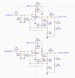
I recently put together my first amp based off of this circuit using the TDA2003a (I know there are better IC's out there). Overall things went well and I got some good sound out of it on the first try, albeit with some obvious issues. Two of these issues started only after I installed a potentiometer for volume control.
The first is a buzzing/popping when no input is connected/poor connection. I presume this is a grounding issue and could maybe be solved or at least minimized with a resistor from signal to ground near the pot? (This happened before I used a pot as well, and I had thought that the 56k resistor in the circuit would mostly prevent this but I guess not).
The second is a constant buzz even when an input is connected, the volume of which changes as I turn the pot. This only started after I added the pot so I think it's a grounding issue?
The third is an additional fainter hum that happens when touching the metal knob on the pot, which I at least think is related to the same grounding issue as the previous problem.
Any advice is appreciated, I can provide more details if that helps!
Thanks!
Attachments
Ground the pot housing.
Maybe the gain is set too high.
It is an old IC, this may have been a problem earlier as well, do a search on the net.
Maybe the gain is set too high.
It is an old IC, this may have been a problem earlier as well, do a search on the net.
could be a problem of your layout - signal and power supply sharing the same routes. Your feedback-Resistors are relatively low in value and they draw a DC-current as you use a single Supply-Voltage. Can you show your Layout?
Your schematic shows a single supply rail (pin3 is 0V) but your TDA2003 + input pin is not being biassed at mid-rail as would be the normal case, rather at 0V. This is a significant problem as audio signals swing both + and -.
R9 and R10 need to be fed from a mid-rail voltage generator circuit - this could be as simple as two Rs and one C.
Having checked TDA2003 DS I see its rather a special case and has its own internal biassing. So R9 and R10 should be removed, no need for the mid-rail generator.
R9 and R10 need to be fed from a mid-rail voltage generator circuit - this could be as simple as two Rs and one C.
Having checked TDA2003 DS I see its rather a special case and has its own internal biassing. So R9 and R10 should be removed, no need for the mid-rail generator.
Not at all.Your schematic shows a single supply rail (pin3 is 0V) but your TDA2003 + input pin is not being biassed at mid-rail as would be the normal case, rather at 0V. This is a significant problem as audio signals swing both + and -.
R9 and R10 need to be fed from a mid-rail voltage generator circuit - this could be as simple as two Rs and one C.
Having checked TDA2003 DS I see its rather a special case and has its own internal biassing. So R9 and R10 should be removed, no need for the mid-rail generator.
Part of the TDA2002/3 "revolution" was that it was the first 5 pin self biasing chipamp ever, invented by genius Engineer Bruno Murari in Milan , working for SGS Ates
All others came out of it, including newer "Op Amp" configuration ones which need external biasing.
As of the OP problem, it´s most probably grounding/shielding/layout caused, circuit by itself is fine.
Not at all.
Didn't read my last sentence? Indeed the TDA2003 is self-biassing which is why it doesn't need R9 and R10, those merely upset its internal biassing.
Read your self-correction afterwards, sorry.
As soon as I started reading the first part I jumped to answer this widely held error.
As soon as I started reading the first part I jumped to answer this widely held error.
I started out assuming it was a TDA2030 but reading the datasheet slapped me out of my delusion 🙂
From the internal schematic, the bias point at the input should be about 2 diode drops above 0V, so around 1.2V and at a typical impedance of 150k. With the 56k resistor to 0V this bias point will be substantially decreased, to around 0.3V and that wont be sufficient bias for the input transistor or its following CCS.
From the internal schematic, the bias point at the input should be about 2 diode drops above 0V, so around 1.2V and at a typical impedance of 150k. With the 56k resistor to 0V this bias point will be substantially decreased, to around 0.3V and that wont be sufficient bias for the input transistor or its following CCS.
Last edited:
I've tried grounding the pot housing and that's seemed to help quite a bit with the buzzing, I'll do more testing when I can.
Thanks so much everyone for the useful info so far!
Thanks so much everyone for the useful info so far!
Everything seems to be working fine and the output power as expected (pretty clean sounding too). You think I should try simply removing those resistors anyway?I started out assuming it was a TDA2030 but reading the datasheet slapped me out of my delusion 🙂
From the internal schematic, the bias point at the input should be about 2 diode drops above 0V, so around 1.2V and at a typical impedance of 150k. With the 56k resistor to 0V this bias point will be substantially decreased, to around 0.3V and that wont be sufficient bias for the input transistor or its following CCS.
- Home
- Amplifiers
- Chip Amps
- Buzzing issue with custom TDA2003a circuit