Hi all,
I have several power amplifiers that are used to run a vibratory shaker table that I own and some of the BUZ210 N-Ch MOSFETs are testing bad. There are nine of the amplifier modules in the controller cabinet with 20 BUZ210s on each module for a total of 180 FETs. I'm looking for a replacement MOSFET to the BUZ210 and have nearly given up on finding one in a TO-3 package. I'm considering spinning a custom PCB to adapt a surface mount MOSFET to the TO-3 mounting holes and heat sink, but I do not know how close I need to match parameters like input capacitance, transconductance, charge, etc.
The specs for the BUZ210 are attached. I'm considering something like the IRFAC50 (TO-3) package, or something like the AOD380A60C. The BUZ210 has an input capacitance of 3800 pF @ 25 Vds. The parts I'm finding that meet Vgs and Id specifications have much lower input capacitance (e.g. 900 pF @ 100 Vds).
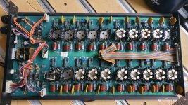
How close do I need to match these other parameters for a power amplifier like this? The amplifier energizes a very large field coil to create a field that moves the shaker table up and down. I also attached a picture of one of the nine amplifier modules. Some of the BUZ210s are removed for testing.
Thanks!
I have several power amplifiers that are used to run a vibratory shaker table that I own and some of the BUZ210 N-Ch MOSFETs are testing bad. There are nine of the amplifier modules in the controller cabinet with 20 BUZ210s on each module for a total of 180 FETs. I'm looking for a replacement MOSFET to the BUZ210 and have nearly given up on finding one in a TO-3 package. I'm considering spinning a custom PCB to adapt a surface mount MOSFET to the TO-3 mounting holes and heat sink, but I do not know how close I need to match parameters like input capacitance, transconductance, charge, etc.
The specs for the BUZ210 are attached. I'm considering something like the IRFAC50 (TO-3) package, or something like the AOD380A60C. The BUZ210 has an input capacitance of 3800 pF @ 25 Vds. The parts I'm finding that meet Vgs and Id specifications have much lower input capacitance (e.g. 900 pF @ 100 Vds).
How close do I need to match these other parameters for a power amplifier like this? The amplifier energizes a very large field coil to create a field that moves the shaker table up and down. I also attached a picture of one of the nine amplifier modules. Some of the BUZ210s are removed for testing.
Thanks!
Attachments
Last edited:
If they are used as amplifying devices rather than switches, the main thing is the SOAR curve. Modern MOSFETs often have Spirito instability (thermal second breakdown) and self-destruct when used in such a manner.
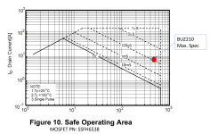
@MarcelvdG thank you for the response. After doing some research I believe that makes sense to me. Please tell me if I understand this correctly. You are saying that assuming the FET is used as an amplifying device rather than a switch, I should make sure that the operating conditions like Id and Vds are in the safe zone on the SOA curve. For example, if the BUZ210 is operated at or near its maximum specifications of 500Vds and 10.5 Id, the SOA curve from a potential replacement FET below probably wouldn't work because the operating condition is not within the continuous duty zone (below the DC curve):
Attachments
The tiny heat sinks would indicate they are not used as linear (heat dissipating) devices but only as switches. But I might be wrong ...amplifying device rather than a switch
@MarcelvdG thank you for the response. After doing some research I believe that makes sense to me. Please tell me if I understand this correctly. You are saying that assuming the FET is used as an amplifying device rather than a switch, I should make sure that the operating conditions like Id and Vds are in the safe zone on the SOA curve. For example, if the BUZ210 is operated at or near its maximum specifications of 500Vds and 10.5 Id, the SOA curve from a potential replacement FET below probably wouldn't work because the operating condition is not within the continuous duty zone (below the DC curve):
Indeed, and modern MOSFETs often have a maximum drain current that drops very quickly with increasing voltage on the DC SOAR curve, or even have no specified DC curve at all. stv has a point about the heatsink size, though.
Thank you both! This is very helpful feedback. Are there other ways I can determine if the MOSFET is being used as a linear device or as a switching device in this circuit? I can eventually power the unit back on and take measurements.

- Home
- Amplifiers
- Solid State
- BUZ210 MOSFET Replacement