Hello,
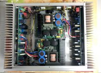
I built a Buermester 956 clone based on Chinese boards and two Connex SMPS600 power supplies.
The amp works very well and is particularly effective with greedy and low sensibility speakers like Dynaudio speakers.
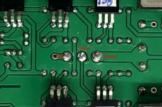
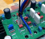
I try to understand the function of the blue trimmer present on the board. I suspect this is the quiescent current setting but I'm not sure because I don't have the schematic. The trimmer is blocked with glue.
Does anyone have experience with this type of amp?
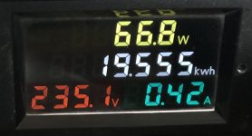
Basically, I try to lower its consumption a little because each board consumes 65W at idle.
Cheers,
I built a Buermester 956 clone based on Chinese boards and two Connex SMPS600 power supplies.
The amp works very well and is particularly effective with greedy and low sensibility speakers like Dynaudio speakers.
I try to understand the function of the blue trimmer present on the board. I suspect this is the quiescent current setting but I'm not sure because I don't have the schematic. The trimmer is blocked with glue.
Does anyone have experience with this type of amp?
Basically, I try to lower its consumption a little because each board consumes 65W at idle.
Cheers,
Attachments

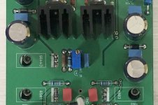
It'll be setting the bias as you say. There appear to be test points for the bias between some of the emitter resistors.
The layout and polarity of the transistors indicates this is a CFP output amplifier, meaning the optimum bias current should be quite small, 10 to 20mA at most per pair of output devices. I suspect this has been preset into class AB hence the high bias currents you are seeing.
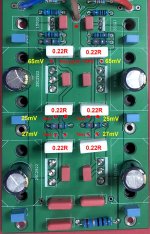
If you read the resistance of the white emitter resistors and monitor the voltage across them as the multi-turn pot is adjusted you'll be able to determine the bias current. For instance with 0.22 ohm resistors 15mA would produce 3.3mV across each resistor.
Since there are two pairs of output devices you'll find slightly different voltages across the resistors of each pair, aim for the average to be say 15mA (but ensure each pair has at least 5mA).
Ideally you'd monitor the output THD while adjusting.
Bias is set with no speakers connected to the amplifier, note.
A caveat - if this amplifier is designed for heavy bias currents (class AB) it may become unstable at very low bias (and oscillate), so go carefully and dont overshoot your target - ideally you'd test with a dummy load at full power to check for stability.
The layout and polarity of the transistors indicates this is a CFP output amplifier, meaning the optimum bias current should be quite small, 10 to 20mA at most per pair of output devices. I suspect this has been preset into class AB hence the high bias currents you are seeing.
If you read the resistance of the white emitter resistors and monitor the voltage across them as the multi-turn pot is adjusted you'll be able to determine the bias current. For instance with 0.22 ohm resistors 15mA would produce 3.3mV across each resistor.
Since there are two pairs of output devices you'll find slightly different voltages across the resistors of each pair, aim for the average to be say 15mA (but ensure each pair has at least 5mA).
Ideally you'd monitor the output THD while adjusting.
Bias is set with no speakers connected to the amplifier, note.
A caveat - if this amplifier is designed for heavy bias currents (class AB) it may become unstable at very low bias (and oscillate), so go carefully and dont overshoot your target - ideally you'd test with a dummy load at full power to check for stability.
Hi Mark!
Thanks for your answer.
I made some test before playing with the two jumpers present on the board (default: GND board to chassis and xlr-neg to GND board).
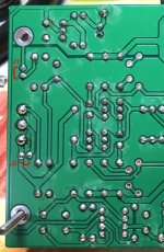
I will look if I have a photo of the underside of the PCBs.
Seems not good to touch the pot without a THD analyser. 😡
Cheers,
Signal just before clipping.

No signal.
PSU: 600mA per polarity for 58v (per board)

Thanks for your answer.
I made some test before playing with the two jumpers present on the board (default: GND board to chassis and xlr-neg to GND board).
I will look if I have a photo of the underside of the PCBs.
Seems not good to touch the pot without a THD analyser. 😡
Cheers,
Signal just before clipping.
No signal.
PSU: 600mA per polarity for 58v (per board)
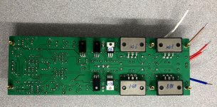
One thing I noticed with the board pictures is that there are only 4 high-current wires to each amp, not the normal 5. 3 for the supply, 2 for the speaker output. Which is worrying as this layout gaffe introduces distortion from the currents going to the amp boards local decoupling caps. These produce small voltage drops along the ground wire that the feedback network cannot see and correct.
Normally there's a star ground on the amp for feedback and speaker and local decoupling.
Normally there's a star ground on the amp for feedback and speaker and local decoupling.
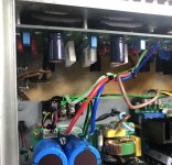
If you look at the top view of the assembled amp, there is an additional heavy black lead that doesn't appear on the posted amplifier board view. It's not clear what this lead connects but perhaps this is the missing ground link?
Hello,
I give you more information on the amp card.
The card has four basic output wires:
Red 15AWG (1.5mm2): +
Blue 15AWG (1.5mm2): -
White 15AWG (1.5mm2): GND
Red 20AWG (0.5mm2): protect
Seems difficult to add another GND line directly on the board for GND speaker output. No big hole and space available.
On my board, I removed the red "protect" wire because I was not using it.
On this page, there is some information about the amplifier board.
The reference machine is the Voice of Berlin 956 full symmetrical X Amp ultra fast power amplifier line 150W * 2 amplifier|Amplifier| - AliExpress
I bought the amp boards alone from another Aliexpress reseller.
The amplifier board also has two jumpers:
J1 : to connect audio GND to chassis.
J2 : to connect XLR NEG to audio GND (for unbalanced use).
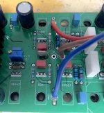
I replaced all soldered jumpers with connectors.
See pictures.
.
I give you more information on the amp card.
The card has four basic output wires:
Red 15AWG (1.5mm2): +
Blue 15AWG (1.5mm2): -
White 15AWG (1.5mm2): GND
Red 20AWG (0.5mm2): protect
Seems difficult to add another GND line directly on the board for GND speaker output. No big hole and space available.
On my board, I removed the red "protect" wire because I was not using it.
On this page, there is some information about the amplifier board.
The reference machine is the Voice of Berlin 956 full symmetrical X Amp ultra fast power amplifier line 150W * 2 amplifier|Amplifier| - AliExpress
I bought the amp boards alone from another Aliexpress reseller.
The amplifier board also has two jumpers:
J1 : to connect audio GND to chassis.
J2 : to connect XLR NEG to audio GND (for unbalanced use).
I replaced all soldered jumpers with connectors.
See pictures.
.
Attachments
Last edited:
More on this.
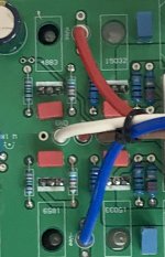
After doing a test, I was able to replace the white GND cable with a large faston connector on which I could connect two 15AWG cables. There was a second smaller hole on the PCB which was at the right distance to put a faston connector. One to go to the power supply GND and another to go to the GND speaker.
With this I will have a direct start connection and I can remove the black connector used to build the GND star.
.
Attachments
Last edited:
I'm sure that the trimmer is for the bias, as it is close to the 2SC4495, which is developed for bias controlling transistor.
Basically, I try to lower its consumption a little because each board consumes 65W at idle.
Cheers,
Are you sure? From the numbers it seems about half that. The meter shows the power consumed from the mains, that must be two boards as well as the transformer/rectifier losses.
Surely the bias is not 600mA per board? 300mA is more plausible.
Jan
The amplifier is currently disassembled to modify the GNDs. As soon as it is reassembled, I will take the power consumed measurements again directly at the 58vDC after the SMPS.
If you have a suggestion on where to test for bias on the board, I'll take it.
This picture was the power consumed from the mains for ONE board + speaker protection module using the SMPS600RxE at 58v.
.
If you have a suggestion on where to test for bias on the board, I'll take it.
This picture was the power consumed from the mains for ONE board + speaker protection module using the SMPS600RxE at 58v.
.
Attachments

Last edited:
Yes, that sounds a good move - shame not double pads for the OUT wire too. Are the extra V+ and V- pads meant for Fastons?
After doing a test, I was able to replace the white GND cable with a large faston connector on which I could connect two 15AWG cables. There was a second smaller hole on the PCB which was at the right distance to put a faston connector. One to go to the power supply GND and another to go to the GND speaker.
And somewhere to hang a scope ground lead fromWith this I will have a direct start connection and I can remove the black connector used to build the GND star.
.
YAre the extra V+ and V- pads meant for Fastons?
Yes, PCB Faston connector fit. But not for the speaker output. Only one 1.5m2 hole is available (brown wire).
Bias is set at about 250mA pr device.A little bit too high. And the amp layout do NOT support that kind of bias setting. As the outputdevices are clustered together. Well. the amps layout suck period. regarding outputdevices.
Hi!
I mesured the power consumed by one board with no signal:
V+ = 512mA
V- = 508mA
For 58.15 VDC at board input.
If you have a suggestion where to measure the bias directly on the board, let me know.
I mesured the power consumed by one board with no signal:
V+ = 512mA
V- = 508mA
For 58.15 VDC at board input.
If you have a suggestion where to measure the bias directly on the board, let me know.
Last edited:
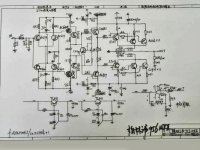
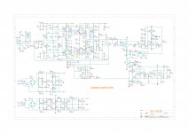
Thanks a lot for the drawings. I've all needed to mesure now.
.
.
Attachments

Last edited:

Hi!
I lowered the bias to 65mV instead of 101mV.
The amplifier heats up much less and the consumption is down to 380mA with 58V. Scope curves are good from 20Hz to 20KHz.
DC at ouput is 1mV.
.
I lowered the bias to 65mV instead of 101mV.
The amplifier heats up much less and the consumption is down to 380mA with 58V. Scope curves are good from 20Hz to 20KHz.
DC at ouput is 1mV.
.
Attachments
Last edited:
- Home
- Amplifiers
- Solid State
- Burmester 956 clone