I’ve started building the Ellam FLEX two-way. Thanks for the reassurance that 400V caps can be used in the crossover design. I’ve sourced Mundorf MCAP 400V DC polypropylene caps with the same µF values as shown in the schematic, instead of the much more expensive Superior Z.
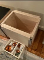
Cabinet work is underway — I’ve done everything so far without power tools, except for a basic IKEA cordless drill, and I don’t even have clamps. The crossover is quite big and heavy, so I’ve decided to keep it outside the box. I’ll share photos soon. Looking forward to any tips or feedback from others who’ve built this design!
Cabinet work is underway — I’ve done everything so far without power tools, except for a basic IKEA cordless drill, and I don’t even have clamps. The crossover is quite big and heavy, so I’ve decided to keep it outside the box. I’ll share photos soon. Looking forward to any tips or feedback from others who’ve built this design!
Attachments

… without power tools! That is cool even if it building without power tools something that, when finished, will need power is a bit paradox 🙂
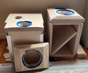
You're absolutely right—it is a bit of a paradox to build something that requires power without using power tools. But since I live in an apartment, I had no choice. It’s difficult to find someone willing to take on small tasks like routing. I drilled a guide hole and carefully cut the speaker opening so the speaker frame sits flush with the front panel. The panel itself has side chamfers at approximately 45 degrees. I cut the boards using a Japanese handsaw, then filled and sanded everything by hand. Without clamps, I used weights for pressure and installed aluminum profiles to keep the panels properly aligned and ensure accurate angles when assembling the four sides.… without power tools! That is cool even if it building without power tools something that, when finished, will need power is a bit paradox 🙂
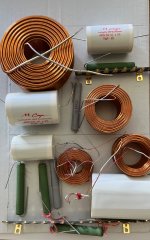
Here’s a photo of one of the speaker crossovers I’am working on. Could you please let me know if the positioning of the coils looks okay? I tried to keep enough distance and avoid bad orientation, but would appreciate your feedback before final assembly. Thanks
Attachments
Troels himself has a lot of information on his site, here’s some:
http://www.troelsgravesen.dk/coils.htm
http://www.troelsgravesen.dk/tips.htm#CONSTRUCTION_OF_CROSSOVERS
He has/had a nice grafic about inductor placement:

Hope this helps!
http://www.troelsgravesen.dk/coils.htm
http://www.troelsgravesen.dk/tips.htm#CONSTRUCTION_OF_CROSSOVERS
He has/had a nice grafic about inductor placement:
Hope this helps!
According to Troels, does that mean cowanaudio does not understand basics of it or...?
https://www.diyaudio.com/community/threads/pcb-or-not-pcb-this-is-a-problem.425129/post-7956802
https://www.diyaudio.com/community/threads/pcb-or-not-pcb-this-is-a-problem.425129/post-7956802
Good question. Troels published measurements, maybe cowanaudio has some too? (I‘d say if they measure as expected or as they should, they‘re good, regardless of other ppl‘s saying.
But I don’t know anything about it.
But I don’t know anything about it.
I do number 8 when prototyping. It really depends what the intention is.
It also depends on the differences in the circuits as well as the subtleties of the devices and their placement. The best way to monitor unintended coupling is to measure it in action.
It also depends on the differences in the circuits as well as the subtleties of the devices and their placement. The best way to monitor unintended coupling is to measure it in action.
Last edited:
It’s clear that there is a general rule of thumb for coil positioning, but the best way to verify it is by measurement. Thank you for the feedback, I’ll try to create a bit more space between the coils and might flip the tweeter section top-to-bottom so that the three coils aren't so close together. I’m planning to mount the crossover externally, fixed to the back of the speaker above the port and cover it all with a thin sheet of plexiglass.
I really like Cowanaudio’s neat sandwich board design — it keeps the wiring underneath hidden, very clean. Lojzek, thank you for sharing that approach as well!
I really like Cowanaudio’s neat sandwich board design — it keeps the wiring underneath hidden, very clean. Lojzek, thank you for sharing that approach as well!
I’m amazed at how effectively self-adhesive bitumen sheets dampen the speaker cabinet walls and reduce resonance — it’s easy to confirm just by doing a simple knock test by hand, before and after applying the sheets.
It almost makes me want to open all my vintage speakers and add it to each one!
It almost makes me want to open all my vintage speakers and add it to each one!
Attachments

- Home
- Loudspeakers
- Multi-Way
- Building the Ellam FLEX by Troels Gravesen