Hi all. Does anyone have any experience with the TDA1560Q, 40W car radio high power amplifier from Phillips?
I refered to the data sheet and there was a test and application diagram to follow. However, I do not know the functions of pin17 (S1) and pin16 (Mode Select Switch). Does anyone know what they are for and what is suppose to be the inputs to these pins? Also, I don't know what voltage ratings to use for the electrolytic capacitors used in the diagrams.
The chip is rated at 40W and I am driving a 30W loudspeaker. Is there any chance of damaging the speaker?
Thanks in advance.
This chips spec is not too good, it is only 10W RMS and is basically an economical way of getting a 40W rating from car power without the cost of a switching power supply
pin 16 Mode Stby/Mute/class B/class H
Can be pulled up for class H and let pin 17 control fall back to class B when too hot
pin 17 S1 is used to manually force class B or class H operation, floating is auto controlled by temperature.
C1 and C2 should be rated at more than 2x supply voltage
This is unlikely to blow a 30W speaker.
The two caps should be rated at about 50 Volts....
The 40 watts is got by the rail booster built into the chips, and is a music power rating, not a 'real' rating. In that sense it should be looked at as 10 watt/ch amp with a 10dB dynamic headroom rather than a pure 40 watt amplifier. Not a bad thing by any means...
The 40 watts is got by the rail booster built into the chips, and is a music power rating, not a 'real' rating. In that sense it should be looked at as 10 watt/ch amp with a 10dB dynamic headroom rather than a pure 40 watt amplifier. Not a bad thing by any means...
Thanks for your replies. I would like to use the full potential of the loudspeaker, driving it to the loudest possible. I initially wanted to use the LM1875 but realised that I need a dual supply of about 25V.
I have a restriction on the avaliable power supply I can provide. Basically I would be using car batteries to drive the amplifier and speaker. It doesn't matter if the batteries dry up within an hour or two since I am using it only for a short period each time and can just replace or recharge the batteries.
Do you think its still worthwhile to use the TDA1560? Or does anyone know of any other chip that is more suitable?
We use this chip in a passenger announcement system on transit vehicles. With a 12 V dc supply, you will get about 24 W RMS into 4 ohms at 1 kHz. The power does drop off at lower frequencies. This chip is not high-end audio. It is designed to give decent specs for car radios operating off of a 12 V supply.
Lloyd
Lloyd
Thanks for your replies. I would like to use the full potential of the loudspeaker, driving it to the loudest possible. I initially wanted to use the LM1875 but realised that I need a dual supply of about 25V.
Then go for LM3875 or even TDA729x
I've been thinking of adding a sub to my car system and after a lot of thought I decided that I need only slightly higher power than the main speaker amp which is about 20 watts (into 4 ohms) per channel. A chip amp being preferable as it cuts out the need for a smps. I find that there have been a few threads on this subject and the TDA1560Q ( whic is sometimes available here ) was discussed. However there seems to be some doubt about capacitor ratings and I had a look at the circuit diagram.
I found this comment in one of the threads :
".......C1 and C2 should be rated at more than 2x supply voltage ...."
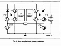
The functional diagram of the TDA1560Q taken from the Elektor March 1995 article on the TDA1560Q is attached. The capacitors C1 and C2 are the ones used to enhance the supply voltage during peak signals.
Take for example the capacitor C1. Under normal conditions it charges up through D1 and T7 to reach a slightly lower voltage than the supply voltage ( say max 14 volts of the battery).
During music peaks the transistor T5 switches on and the capacitor C1 will appear in series with the supply voltage and the rail voltage seen by the output circuit will now be 28 volts ( battery voltage plus voltage across C1). D1 will be reversed
biased and so it will stay 'off'. However the voltage across the capacitor which was 14 volts will slowly deplete itself as the load draws current. Under music conditions the drop would be minimal. Under worst case conditions if the capacitor discharges fully it will get reversed charged by the battery but will be only up to the diode drop of D1 about 0.6V ( - V sat of T5 )as the condition will turn on D1.
So it appears that C1 ( and C2 ) do not need to be rated higher than the battery voltage and typically a 16 V rated capacitor is all that is required.
I found this comment in one of the threads :
".......C1 and C2 should be rated at more than 2x supply voltage ...."
The functional diagram of the TDA1560Q taken from the Elektor March 1995 article on the TDA1560Q is attached. The capacitors C1 and C2 are the ones used to enhance the supply voltage during peak signals.
Take for example the capacitor C1. Under normal conditions it charges up through D1 and T7 to reach a slightly lower voltage than the supply voltage ( say max 14 volts of the battery).
During music peaks the transistor T5 switches on and the capacitor C1 will appear in series with the supply voltage and the rail voltage seen by the output circuit will now be 28 volts ( battery voltage plus voltage across C1). D1 will be reversed
biased and so it will stay 'off'. However the voltage across the capacitor which was 14 volts will slowly deplete itself as the load draws current. Under music conditions the drop would be minimal. Under worst case conditions if the capacitor discharges fully it will get reversed charged by the battery but will be only up to the diode drop of D1 about 0.6V ( - V sat of T5 )as the condition will turn on D1.
So it appears that C1 ( and C2 ) do not need to be rated higher than the battery voltage and typically a 16 V rated capacitor is all that is required.
Attachments
- Status
- Not open for further replies.
- Home
- Amplifiers
- Chip Amps
- Building power amp using TDA1560