Hi guys,
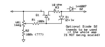
Long time lurker , I'm trying to build an ECL82 based tube amplifier based on this circuit.

I used an PT from an old EL84 based amplifier

On the B+ I'm getting 380v at no load with a 1k 10w as the dropping resistor @RS is that normal? The secondary of the PT is around 270v. For C20 n C21 is a 47uf 450v cap.
Long time lurker , I'm trying to build an ECL82 based tube amplifier based on this circuit.
I used an PT from an old EL84 based amplifier
On the B+ I'm getting 380v at no load with a 1k 10w as the dropping resistor @RS is that normal? The secondary of the PT is around 270v. For C20 n C21 is a 47uf 450v cap.
Yes that is normal, the peak value of the AC waveform is 270 * 1.41 = 381V. The voltage will only drop when the amplifier circuit draws current.I'm getting 380v at no load is that normal?

https://web.archive.org/web/20130915184532/http://www.lh-electric.net/projects/tiny3w.html
It says 270 Volts plate voltage is what is needed.
Don't want to destroy the tube.
It says 270 Volts plate voltage is what is needed.
Don't want to destroy the tube.
If the amplifier consumes -for example- 50mA for each channel (100mA for both), on the 1k Rs resistor the voltage drop is 100V (1k*0.1A), so B+ -about- 280V (lower, because PT secondary voltage also decreasing if current increasing).
Try to test the PSU with 2k7 50W dummy load resistor and measure B+ voltage.
Try to test the PSU with 2k7 50W dummy load resistor and measure B+ voltage.
In this case Rs will be very hot, at least a 25W rating wirewound resistor were needed.
A better option is to disassemble the transformer and remove some turns from the secondary.
A better option is to disassemble the transformer and remove some turns from the secondary.
1k should work for Rs if there are two tubes -are you building in stereo? You'll need something like 2.2k for only one tube. Really your transformer voltage is too high for this project, but it will work.It says 270 Volts plate voltage is what is needed.
Don't want to destroy the tube.
Last edited:
Remember the voltage rating for the tube, is across the tube measuring from the plate pin to the cathode, not from the plate pin to ground. Unloaded voltages don't really tell you much either. And honestly, tubes can handle being "over volted" pretty well within reason, excess current/dissipation is what kills them. I'd build it and pull it up slowly on a variac to be safe. Also the PSUD2 power supply simulation software works very well.
Thanks guys, currently building only one channel now. Just to check if everything works. Will try and get a dummy load. Or I'll sacrifice one tube to the gods. 😉
A variac would be helpful here, and is generally a good dervice to have around if you're building your own projects.
I'm surprised not to see it stated more often, but the easiest way to lower the B+ is to use a smaller first capacitor. The sensitive range is roughly between 0.47uF and 3uF. You can get a B+ range that is usually wide enough for most purposes. No need to take windings off the mains transformer.
But to do this properly you should be using a CLCRC supply. Just use an appropriate Hammond choke - nothing fancy.
But to do this properly you should be using a CLCRC supply. Just use an appropriate Hammond choke - nothing fancy.
I must disagree a bit with this last part. Decreasing the first C works but it puts more strain on the choke, increasing the risk for mechanical noises from the windings and the core. 0,47uF is enough to make a lot of chokes more or less silent but it depends on several factors, including the build quality of the choke.Just use an appropriate Hammond choke - nothing fancy
Try it, but be aware that you might experience a buzzing sound from the choke.
I built that ecl82 amp when I was 9, now 62 years ago. transistors were not economically available... I just parts obtained from dissection of old radios.
I've used many, many Hammond chokes for years and none of them have buzzed. They do their job well.I must disagree a bit with this last part. Decreasing the first C works but it puts more strain on the choke, increasing the risk for mechanical noises from the windings and the core. 0,47uF is enough to make a lot of chokes more or less silent but it depends on several factors, including the build quality of the choke. Try it, but be aware that you might experience a buzzing sound from the choke.
But as you say, it's a possibility with chokes.
Several factors are involved, and sometimes it only takes very small changes to go from buzzing to quiet or vice versa. I've learned to torture tests chokes before I use them in anything close to a choke input filter; a couple of years ago I was designing LCLC filters for 6S4S filaments, using Hammond 28mH 3A chokes in the first position. I had one (made in Canada) on the shelf, this particular one was perfectly up to the task so I ordered four more for the actual build. These were made in China and buzzed quite loudly under the exact same circumstanses.
Once you connect the amplifier circuit and the tubes begin conducting, the B+ voltage will no longer remain at its no-load value of 380V. Instead, it will drop to a stable operating voltage, typically within the range of 250-300V, depending on the circuit’s overall current draw and the characteristics of your power transformer and rectifier circuit. This voltage drop occurs because the tubes act as active loads, drawing current and thereby reducing the voltage across the power supply filter components.Hi guys,
Long time lurker , I'm trying to build an ECL82 based tube amplifier based on this circuit. View attachment 1428062
I used an PT from an old EL84 based amplifier
View attachment 1428064
On the B+ I'm getting 380v at no load with a 1k 10w as the dropping resistor @RS is that normal? The secondary of the PT is around 270v. For C20 n C21 is a 47uf 450v cap.
To make sure that the power supply is functioning correctly, measure the voltage drop across the 1kΩ dropping resistor (Rs). This will allow you to estimate the current flowing into the amplifier circuit using Ohm’s Law (I = V/R). For instance, if you measure a 50V drop across Rs, the current draw would be 50V / 1000Ω = 50mA. This measurement can help you verify whether the amplifier is drawing the expected current and ensure that your power supply is appropriately sized.
Regarding your power supply capacitors (C20 and C21), their 47µF capacitance at 450V is sufficient for filtering and smoothing the rectified DC voltage. However, if your B+ voltage exceeds 450V due to variations in transformer output, light loading, or inrush conditions, these capacitors could be operating close to their maximum rating, which may reduce their lifespan or lead to failure over time. To provide an additional margin of safety, you may consider upgrading to capacitors rated at 500V or higher, which would offer improved reliability and protection against unexpected voltage surges. If you want to print a PCB of your amplifier, you can take a look here to get an idea about pricing. https://www.allpcb.com/blog/pcb-ordering/pcb-cost-per-unit.html
- Home
- Amplifiers
- Tubes / Valves
- Building my first tube amplifier Lowering B+