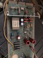
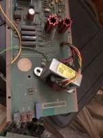
I have a retired microphone amplifier motherboard from BBC. It has ll1538 input transformer, sowter output transformer, class a driver circuit and 5534 amplifier.
Now I want to put it into the chassis to continue its service, but I lack a 48V phantom power supply. I heard that this 48V power supply has a great impact on the recording quality, so I want to build a low-noise 48V phantom power supply, but the commonly used LM317 can only output 40V at most. Is there any other scheme recommended?
Now I want to put it into the chassis to continue its service, but I lack a 48V phantom power supply. I heard that this 48V power supply has a great impact on the recording quality, so I want to build a low-noise 48V phantom power supply, but the commonly used LM317 can only output 40V at most. Is there any other scheme recommended?
Attachments
It is probably more important to have low noise than low ripple for a phantom power supply. This is because the supply is presented to both the (+) and (-) differential inputs of the preamp and supply irregularities (hum and noise) cancel out to the extent of the common mode rejection ration of the preamp, which is always better at low frequencies than high. An RC/RC/RC filter, not a chip regulator, is a better approach. See the link below for ideas:
https://www.google.com/search?q=48V...=img&ei=AQTpYey3AvyFz7sPsbaR-AM&client=safari
https://www.google.com/search?q=48V...=img&ei=AQTpYey3AvyFz7sPsbaR-AM&client=safari
Actually an LM317 can handle 40 V between its input and output, so you can go a bit higher as long as the output is never shorted and you don't make the output decoupling capacitor too large. Besides, there is an LM317HV that goes up to 60 V between input and output.
You are not going to keep the unloaded phantom supply voltage in its specified 48 V +/- 4 V range with +/- 10 % mains variations without some sort of regulator, but combining a regulator with an RC filter can be a very good approach.It is probably more important to have low noise than low ripple for a phantom power supply. This is because the supply is presented to both the (+) and (-) differential inputs of the preamp and cancels out to the extent of the common mode rejection ration of the preamp, which is always better at low frequencies than high. An RC/RC/RC filter, not a chip regulator, is a better approach. See the link below for ideas:
https://www.google.com/search?q=48V...=img&ei=AQTpYey3AvyFz7sPsbaR-AM&client=safari
Thank you for your suggestion. I read the manual of 317hv. Its 10hz-10khz output noise is 0.003% of the output voltage, 48V x 0.003 = 144mv square root Hz. It seems that the output noise is still very large. I don't think IC output seems to be a good scheme. Maybe I need to consider the scheme of voltage reference + power tube current expansion?Actually an LM317 can handle 40 V between its input and output, so you can go a bit higher as long as the output is never shorted and you don't make the output decoupling capacitor too large. Besides, there is an LM317HV that goes up to 60 V between input and output.
Sorry, I forgot to count the percentage. Actually, it should be 48V * 0.000003 = 144uv square root hertz. Is this correct? Adding RCRC filtering is a good suggestion.You are not going to keep the unloaded phantom supply voltage in its specified 48 V +/- 4 V range with +/- 10 % mains variations without some sort of regulator, but combining a regulator with an RC filter can be a very good approach.
I know this is a DIY oriented forum, but unless you are itching for a project , you can buy commercial 48v phantom supplies for under $30. In a box, with XLR in and out, ready to go. A couple examples:
https://www.sweetwater.com/store/de...VCpSzCh3_SA_yEAQYASABEgI4ZvD_BwE&gclsrc=aw.ds
https://www.amazon.com/EBXYA-Conden...locphy=9017227&hvtargid=pla-942780789053&th=1
Of course you can spend more than that, perhaps more features interest.
https://www.sweetwater.com/store/de...VCpSzCh3_SA_yEAQYASABEgI4ZvD_BwE&gclsrc=aw.ds
https://www.amazon.com/EBXYA-Conden...locphy=9017227&hvtargid=pla-942780789053&th=1
Of course you can spend more than that, perhaps more features interest.
No, I won't consider this commercial product. The internal circuit of this product is simple. It must use DC DC boost circuit internally. It will have terrible high-frequency noise. I think the design of this BBC microphone amplifier board is very good. It is worth using a good power supply.
报错 笔记
报错 笔记
It's 1.44 mV over 9990 Hz, so on average just above 14.4 uV/sqrt(Hz).Sorry, I forgot to count the percentage. Actually, it should be 48V * 0.000003 = 144uv square root hertz. Is this correct? Adding RCRC filtering is a good suggestion.
With, say, 60 dB of common mode suppression, that's a totally unacceptable 14.4 nV/sqrt(Hz) of differential noise. You indeed need a filter.
One approach would be decoupling the reference resistor of the LM317HV, adding diodes if needed to prevent damage at switch off. Another is to put an RC filter between the regulator and the microphone.
A 48 V phantom supply is normally connected via two well-matched 6.8 kohm resistors to XLR pins 2 and 3, or via a single 3.3 kohm resistor to the centre tap of the primary of the input transformer of the microphone amplifier.
In the latter case, instead of using 3.3 kohm, you could use 2.7 kohm in series with 680 ohm, with the 680 ohm on the side that connects to the regulator, and put a 100 uF electrolytic capacitor from the point where the resistors are connected to each other to ground. That will suppress noise from about 3 Hz onwards.
"I heard...."I heard that this 48V power supply has a great impact on the recording quality,
Unless the microphone is crap, the 48V has almost no effect on "sound". That's the base concept behind "Phantom". In the old days they ran a third voice-circuit between two other voice-circuits the same way, despite tight cross-talk specs.
Yes, buy a not-crap 48VDC supply and add 100 ohms plus 100uFd filtering. (I have used less in a very silent concert hall.)
Thank you for being the voice of reason.👍Unless the microphone is crap, the 48V has almost no effect on "sound". That's the base concept behind "Phantom".
One (of many) points overlooked in this thread is that the 48V DC is fed, via largish resistors (6.8k, say), to the output of the mic preamp, which if properly designed, will have an output impedance of a few ohms.
This creates a voltage divider, that drastically reduces any noise or ripple that was on the 48V source. If, say, the output impedance of the preamp is 6.8 ohms, and you feed the DC to it via a 6.8k resistor, that's 60 dB of noise attenuation right there. And that's even before you add any additional phantom power noise filtering.
Let me add that it is a LOT easier to filter away 100 kHz ripple than 60 Hz ripple. This means it is easier to get good noise performance from a switching supply, particularly if it is external.Yes, buy a not-crap 48VDC supply and add 100 ohms plus 100uFd filtering.
A typical ripple spec for a contemporary switching power supply is 100 mV p-p @ 100 kHz. A series 100 ohm resistor and a 10uF ceramic cap to ground is enough to knock down 100 kHz ripple by a whopping 56 dB. Put a 100uF electrolytic cap in parallel with the 10uF ceramic cap if you want to make sure any traces of audio-frequency ripple are filtered too.
Putting a larger-value electrolytic cap (to handle low frequencies) in parallel with a small-value ceramic cap (to handle high frequencies) was standard practice for small-signal audio electronics for decades. Maybe it's been forgotten lately, like so many other good engineering practices developed long ago.
Here's a tiny 10uF ceramic cap (100V rated) that costs $4.40 USD: https://www.digikey.com/en/products/detail/tdk-corporation/FA23X7S2A106KRU06/9991506
If you're willing to use a similar 50V cap the cost drops to $1.38, but a 50V rating is a bit too close to a 48V power rail for comfort.
-Gnobuddy
Input of the mic preamp, you mean? I've never seen a condenser microphone with 6.8 ohm output impedance, 100 ohm is more typical.
More to the point: fed BALANCED to both wires so the crap will cancel-out. That's why we used to do it as a transformer center-tap (the winder can turns-count very accurately); today we take those two 6k8 from the 1% (or better) bin.48V DC is fed, via largish resistors
I know of head-amps with <10 Ohms Zout; they make minor errors into some transformer-input preamps so are often swamped-up to a hundred ohms. I also know some headamps with real high Zout (which makes other trouble, but the penny was saved).
However, as you hint, basic notions of balance and impedance and designing to minimize flaws have been drowned-out in interweb echo.
Yes, and if 99.9 % of the crap cancels out, you still have too much noise, assuming an LM317HV supply without reference resistor decoupling or filtering. Anyway, a simple RC filter will fix that.
By the way, a 10 uF class 2 ceramic SMD capacitor is only 10 uF at 0 V. It's less at 48 % of its nominal working voltage, how much less depends on the exact model.
By the way, a 10 uF class 2 ceramic SMD capacitor is only 10 uF at 0 V. It's less at 48 % of its nominal working voltage, how much less depends on the exact model.
If 'only' 99.9% is cancelled the CMRR of differential input of the preamp must be rather crappy.Yes, and if 99.9 % of the crap cancels out, you still have too much noise,
Not necessarily. There is also the mismatch in the phantom supply circuit (between the two 6.8 kohm resistors if two resistors are used) and in the microphone's output circuit.
It is a conservative value, though. Suppose you have 6.8 kohm + 1 % on one side and 6.8 kohm - 1% on the other side while the microphone output behaves as two perfectly matched 50 ohm resistors to ground. There is a common mode attenuation of 137 times then, but due to the resistor mismatch, the transfer from the phantom supply to the differential microphone output voltage is about 2 % of 1/137, roughly 0.00015, about 77 dB rather than my guesstimated 60 dB.
Still, this assumes perfectly matched positive and negative microphone output impedances. No idea how well those match in real life, but definitely not perfectly.
Last edited:
You should consider the PSRR of the mic amp stage itself when considering system noise. If you have say 25nV/rt Hz spot noise but the amplifier itself has 80 dB PSRR then you will be ok - the input referred noise will be negligible.
Even though resistors might have a ±1% tolerance band, in any batch they are usually quite tightly matched not all over the place like your example. But in any case when I worked in professional audio nobody would just use 1% resistors out of a box for phantom power, they were always selected as matched pairs using a decent resistance bridge; likewise the input resistors for differential circuits. It's a no-brainer really.Not necessarily. There is also the mismatch in the phantom supply circuit (between the two 6.8 kohm resistors if two resistors are used) and in the microphone's output circuit.
- Home
- Live Sound
- Instruments and Amps
- Building a microphone amplifier