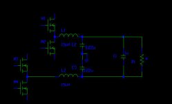
my class d design:
(1) triangle wave 300kHz (PWM)
(2)15V Vcc to the FULL H-bridge
(3)the output filter is butterworth 2nd order with bridge tied load configuration(BTL)
It is very strange.
When the freq of sin wave below 10kHz is applied as audio input , the output peak-peak sin wave is about 1V to 15v.
When the freq of sin wave increases from 10kHz, the output peak-peak voltage starts to increase.
As the input sin wave with freq 20Khz, the output peak-peak voltage becomes larger than 30V(about -10V to 30V).
I know that using BTL configuration, the output voltage will double.
However, in my design, why input signal below 10kHz cannot have double output voltage?
Why the output signal becomes larger as its freq starts to increase from10kHz?
Maybe I have wrong concept. Please help me. Thanks.
...very urgent...
thanks
Attachments
I guess you're not using feedback after the filter. It sounds as if your filter is at too low a frequency, and you're seeing the effects of resonance in the filter.
Your filter will be self-resonant at about 25kHz, but if you're using a 4R load then then resonance will be fairly low-Q, so you shouldn't see to much of an increase. Perhaps I was wrong in my first reply, and it's not the filter, but something else wrong.
more information of my design:
the feedback path is drawn before output filter
inductor: Toroidal Inductors
capacitor: C1 : WIMA MKP 1uF
C2,C3 : electrolytic 0.22uF
NMOS: BUZ11
More importantly:
the filter --- no problem in single-ended configuration, the flat magnitude response in audio freq band (below20Khz).
i.e. C1 is eliminated, C2,C3 :electrolytic 0.68uF
---urgent---
thanks
Do you really mean electrolytic? I think this would be a bad idea as I doubt if a small electrolytic would cope with the ac switching current in them. They are only 0.22uF, you can easily fit film capacitors there.
Hi Ted
Are you measuring without load ? In this case the rising response will come from the filter's resonance which is just below 30 kHz.
Regards
Charles
Are you measuring without load ? In this case the rising response will come from the filter's resonance which is just below 30 kHz.
Regards
Charles
I changed C2 and C3 as a monolithic 50V cap 0.22uF..instead of electrolytic cap.
But the same result,same waveform were obtained.(i.e. after input sin wave increased from 10khz, the amp of output waveform started to increase)
Could anyone have any futher suggestion?
---urgent---
thanks
But the same result,same waveform were obtained.(i.e. after input sin wave increased from 10khz, the amp of output waveform started to increase)
Could anyone have any futher suggestion?
---urgent---
thanks
Ted,
I would bet that your multi-turn resistor is way too inductive - I run a quick simulation of the filter values you posted, and the filter response is pretty much correct when driving a 4 ohm load.
Find a non-inductive load for testing and use film caps in place of the electrolytics.
John
Edit, have you tried to measure the inductance of your load at 4 Ohms setting - I would not be surprised if it’s greater then your 15uH inductors...
Find a non-inductive load for testing and use film caps in place of the electrolytics.
Good idea ! Additionally a Zobel might not be out of place !
Regards
Charles
Hi Ted,
Using electrolytics as mention already is an extremely bad idea - I guess your using them as your under some cost constraints - but if costs is so critical then I would suggested (very reluctantly) to use ceramic caps - But Pls. don't tell anybody that I said that.
Unless the electrolytics have a low ESR at the switching frequency, internal heating will evaporate the electrolyte over a short time, and these caps will fail very quickly – seen it in many a cheap SMPS’s from China.
John
Hi Charles,
Do you have any experience / recommended values for Zoble components? I was thinking of adding an external switchable Zoble for speakers which have a steeply rising inductance at HF.
I don't have the issue as I use ESL's (the opposite in fact), however most budget box speakers have a rising impedance at HF - good for Class A/ AB amps, but not good for Class D.
John
Personally I would use values that keep the amp stable in a no-load situation. I.e. I would regard flatness of frequency response secondary to safety.
One must never forget that an LC lowpass without load is seen as an LC series tank circuit (i.e. almost a short at resonance). So the snubber should be dimensioned for minimizing this effect IMO.
If the snubber is just there to achive response flatness (with load connected) however then I would dimension it like the ones used for driver impedance linearisation. If you try to compensate for Rdc = 6 =hms and Lvc = 100 uH (as average values) this would give a capacitor of 2.7 uF approx which isn't what I would call small.
Regards
Charles
John
I just left the lab today but I will use ---MKT 270Vac cap--- for C2,C3 in the coming Sunday.
Ted
I just left the lab today but I will use ---MKT 270Vac cap--- for C2,C3 in the coming Sunday.
Ted
Ted,
The Caps. will help – but I suspect that the load is very inductive – so more important to find a non inductive load.
Have a good weekend,
John
The Caps. will help – but I suspect that the load is very inductive – so more important to find a non inductive load.
Have a good weekend,
John
Finally, I use the 4" speaker as the load.
The peak to peak voltage of output filter is corrected.
Audio input (sin) adjusts from few hurdard freq to 20kHz, the output (maX peak volatge)only slightly decreases about 3 or 4V.
The peak to peak voltage of output filter is corrected.
Audio input (sin) adjusts from few hurdard freq to 20kHz, the output (maX peak volatge)only slightly decreases about 3 or 4V.
- Status
- Not open for further replies.
- Home
- Amplifiers
- Class D
- BTL output filter