http://www.edn.com/contents/images/45890.pdf
This is dicussing about it, words ans maths only.
What do you think ? Would you try using such a design for an audio amplifier ?
This is dicussing about it, words ans maths only.
What do you think ? Would you try using such a design for an audio amplifier ?
I don't know this topology, but I do see it being used in a variety of power amps.
Seems to be a powerful technique to get the benefits of high open loop gain with high voltage capability and with good current capability, if the buffer is added.
Seems to be a powerful technique to get the benefits of high open loop gain with high voltage capability and with good current capability, if the buffer is added.
lots of floating power supply power amps using op amp inputs - QSC
A community dedicated to helping everyone learn the art of audio. Projects by fanatics, for fanatics! - Search Results for floating supply amplifier
bootstrapping the op amp ps can be done - non-obvious stability issues from the positive feedback - some not modeled by common manufacturer's Spice models - the sims can wrongly predict stable operation where the real circuit oscillates
There are generally two types of bootstrapped opamp architectures, feed-forward and feedback.
The feed-forward type is faster and more stable, and generally runs open loop. The feed-back type can be designed much more linear and accurate, but must be rolled off to avoid de-stabilizing the loop.
Feedback bootstrapping techniques are used frequently in DMM's. Feedforward is used a lot in high speed applications.
Bootstrapping can also drastically increase the common-mode impedance of your op-amp, as well as dropping the apparent common mode input capacitance.
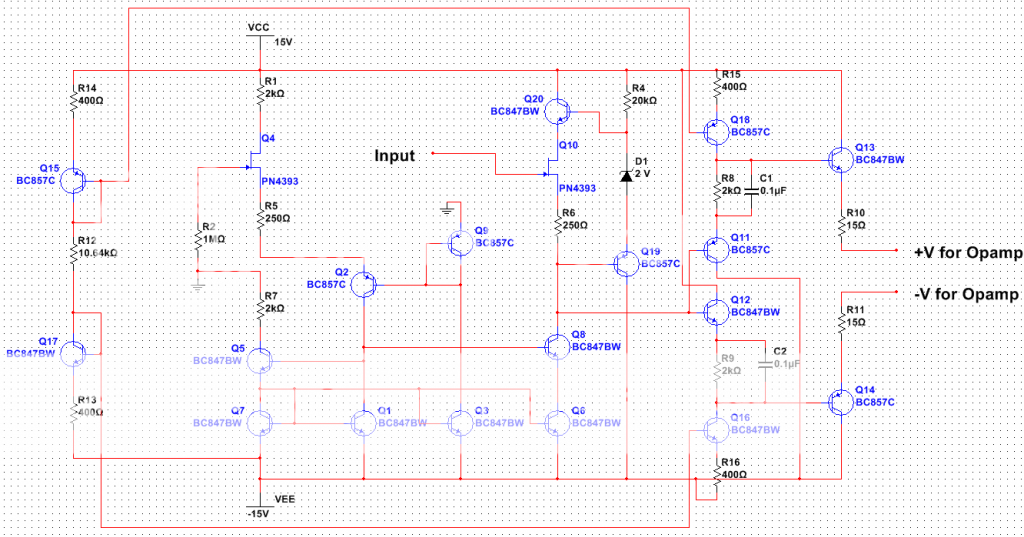
Since it's my first post, here's one I did awhile back. It's feedforward, and provides op-amp rails that are +5V and -5V reference to the input. The input is meant to be connected in parallel with the non-inverting input of the op-amp it is bootstrapping so the signal not only swings the op-amp, it swings the rails too. I've taken care to keep the input impedance very high. At DC, it's greater than a teraohm. It's still upwards of a megaohm at 1Mhz. The -3dB point of that circuit is around 100Mhz and can be made higher if you don't might eating more quiescent current. The + and - offset of the output voltages can be easily adjusted by increasing or decreasing R8 and R9.
The feed-forward type is faster and more stable, and generally runs open loop. The feed-back type can be designed much more linear and accurate, but must be rolled off to avoid de-stabilizing the loop.
Feedback bootstrapping techniques are used frequently in DMM's. Feedforward is used a lot in high speed applications.
Bootstrapping can also drastically increase the common-mode impedance of your op-amp, as well as dropping the apparent common mode input capacitance.
Since it's my first post, here's one I did awhile back. It's feedforward, and provides op-amp rails that are +5V and -5V reference to the input. The input is meant to be connected in parallel with the non-inverting input of the op-amp it is bootstrapping so the signal not only swings the op-amp, it swings the rails too. I've taken care to keep the input impedance very high. At DC, it's greater than a teraohm. It's still upwards of a megaohm at 1Mhz. The -3dB point of that circuit is around 100Mhz and can be made higher if you don't might eating more quiescent current. The + and - offset of the output voltages can be easily adjusted by increasing or decreasing R8 and R9.
An externally hosted image should be here but it was not working when we last tested it.
are you an IC designer? - descrete circuit builders don't often build mirrors without degeneration unless buying matched monolithic transistor arrays
and is turning the 1 Meg R Vnoise into bias current a good idea?
for ~ 2 V most would use LED - true Zener at such low V are poor V regulators
but the fet may want more Vds anyway to get out of triode region, but stay low enough to avoid the hot carrier noise problem
Cap bootstrapping a split R4 would be a better ccs, allows AC swing to the rail
and I have used zener/active shunt Vreg across the floating supply - why not improve on the supply rather than copy its noise/ripple to the bootstrapped suppiles
Last edited:
Haha, nope, not an IC designer. You are right about the need for emitter degeneration, it's just not in there.
As far as the 1Meg goes, yeah, it will add noise. It should ideally be changed to something close to what you expect the source impedance to be, to help with offset and drift.
Good call on the zener too. If I actually had to use this circuit, I'd probably use something else, maybe a TL341. The lightly biased zener will add noise. Actually, for that matter, I might just use diodes.
The circuit, overall, though is designed to be a very fast open-loop buffer. Sure you can add something in there to improve the supply noise on it's way through. Doing it without sacrificing speed is another thing.
I am curious where you learned about different bootstrapping topologies
I have studied, posted a little in http://www.diyaudio.com/forums/solid-state/45794-high-loop-gain-composite-op-amp-circuits.html
but most of what I've found is scattered in articles, app notes, different journals, authors, spread over decades with years going by without anything new
any good refs? - Dimitri Danyuk is one good source of these circuits
Last edited:
Learned mostly on the job 😉
I forgot to mention feedback bootstrapping can give a nice bump in linearity of your op-amp as well, largely because the operating point of the input stage relative to the supplies stays constant, versus swinging the input stage operating point with fixed supplies.
I peeked at your composite op-amp thread. The composite idea has been around for awhile. Basically relies on the idea of distortion being a RTI error. Therefore, by adding an f-ton of gain in the loop around it, you divide those errors by the gain. Add more gain, get less error.
Linear tech did an app note with a composite op-amp as the heart of a wein bridge oscillator to get a 1 Khz sinewave generator that had extremely low distortion. Of course, the tricky part in a sine wave generator is not gain, it's stabilization without distortion, but that's a whole different discussion.
Anyway, the high gain approach is one way to kill distortion. The other is to use every trick you can think of to linear-ize the input stage, for 2 reasons. 1, there is less error to correct from the get go, 2, when the op-amp starts to run out of gain, you have the better linearity of the input stage to fall back on. The AD797 is a good example of this. It's not much more than a very nicely linearized input stage with a lot of gain and a follower stage. There aren't extra gain in between the two.
I show a "feedforward" bootstrappped supply op amp scheme in that thread
dimitri (his user name here) has a couple of relatively recent articles: http://www.epanorama.net/sff/Misc/O...g to reduce distortion in op-amp circuits.pdf
dimitri (his user name here) has a couple of relatively recent articles: http://www.epanorama.net/sff/Misc/O...g to reduce distortion in op-amp circuits.pdf
Bootstrapped Op Amps *are* regularly used in the Music Instrument world.
One big fan of them is Fender.
Here you see the Deluxe 112 Guitar Amplifier, where a bootstrapped/floating PSU MC1436 Op Amp drives the output TIP142/TIP147.
It's fed +/- 25V rails at rest, but those voltages follow the speaker out voltage thanks to capacitors C37/38.
One big fan of them is Fender.
Here you see the Deluxe 112 Guitar Amplifier, where a bootstrapped/floating PSU MC1436 Op Amp drives the output TIP142/TIP147.
It's fed +/- 25V rails at rest, but those voltages follow the speaker out voltage thanks to capacitors C37/38.
An externally hosted image should be here but it was not working when we last tested it.
- Status
- Not open for further replies.
- Home
- Amplifiers
- Solid State
- Boostraping your op amp yields wide voltage swing