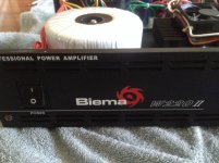
A friend has asked me to help resurrect an obsolete Australian built power amplifier.
It is a solid state 220watt power amp used by djs in the late 90s. We are hoping it is still worth the effort and cost!
The problem is one channel appears to be faulty. When the amp was given to him, the previous owner advised using a bypass jack option at the input instead of RCA connecters as the rcas were damaged.
It seemed like an easy fix at the time easily solved with a pair of rca connectors. However, I am suspecting that when the original plastic bodied rcas were damaged, a channel was compromised.
When turned on, even at very low volume settings, there is an audible hum.
One channel seems to play ok, but the hum remains in the background and increases with an increase in volume. If the Channel B rca is unplugged the output is quiet but audible - over the music.
As soon as the second rca is inserted into the socket - the hum returns.
If cables are switched around - the problem persists.
I considered that I may have mixed up the jumpers off the pcb during rca upgrade - but that was checked and it did not solve the problem.
What I have tried:
1) I tried switching the speaker connections around -
2) i removed one rca and then the other - when upper rca plug was removed, the amp hummed and audio output stopped.
3) I removed the other rca cable and the music played clearly. Hum stopped
4) I removed the jumpers i installed between pcb and rca sockets and discovered that when I removed the common ground soldered to the rca sockets, the amp plays clearly on the one channel to which the ground is connected. The amp hums when the ground is connected to the the second channel input.
I am hoping the A channel is not blown!! But it now seems a real possibility.
Tests were run playing a cd player through a mixer and into the power amp to speakers OR using an ipod, plugged into a passive attenuator/pre-amp and rca connections from passive pre-amp to power amp. In both setups, the problem persisted with the same symptoms.
Attached are some pics of the power amp and schematics - according to the suppliers of this amp, the schematic 2 is an updated version.
Any help and suggestions would be appreciated.
Thank you.
Attachments
Last edited:
Try to isolate the RCA's from the chassis. Unscrew the RCA's and test them hanging.
What happens if You use the jacks since they appear insulated ?
What happens when You use the switch SW1, It seems a ground lift and not a limiter like marked in the schematic?
Version 2 uses a 100 ohm resistor to ground the input sleeve, so loading the source ???
Replace those speaker jacks with speakons ASAP, You don't want to feed a speaker jack onto a mixer input.
Last edited:
Ok.
I tried isolating the RCA's from chassis and testing them- both connected hanging out of the back of the chassis.
When I use channel A - no audio apart from loud hum!
When I use channel B - Audio with RCA connected - hum reduces and soft audio can be heard.
Removed - Ground connection from Channel A rca - hum dropped even softer.
No hum with channel A rca (cable unplugged)
Repeated tests using the Ground/Lift switch - no improvement.
Finally removed disconnected Channel B and resoldered Channel A and retested Channel A alone; very loud hum. Ground/Lift switch made no difference.
Do the jacks work ? If they work check Cables for continuity / Connectors / cracked or bridged solder pads.
Check for DC on the output. Anything over 50 or 100 mV leads us to bad output drivers.
Check for DC on the output. Anything over 50 or 100 mV leads us to bad output drivers.
Sorry, could you specify which jacks you are referring to?
The cables used were from a stereo system in daily use and the jacks were also used on a similar PA amp that served as a backup.
I will check for DC on the output. Thanks for the direction.
The cables used were from a stereo system in daily use and the jacks were also used on a similar PA amp that served as a backup.
I will check for DC on the output. Thanks for the direction.
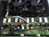
it would require some disassembly but i would remove the input board and inspect the solders on the input jacks on the foil side of the board, stress cracks from patching and unpatching the input or an inadvertent pull can crack solders.
with the description of symptoms you gave that would be the first place i would look.
can't tell because of the blurry pic but it seems the RCA jacks are a retrofit, as in not original.
does this amp have a "bridging" switch?
with the description of symptoms you gave that would be the first place i would look.
can't tell because of the blurry pic but it seems the RCA jacks are a retrofit, as in not original.
does this amp have a "bridging" switch?
Last edited:
it would require some disassembly but i would remove the input board and inspect the solders on the input jacks on the foil side of the board, stress cracks from patching and unpatching the input or an inadvertent pull can crack solders.
with the description of symptoms you gave that would be the first place i would look.
can't tell because of the blurry pic but it seems the RCA jacks are a retrofit, as in not original.
does this amp have a "bridging" switch?
Coincidentally, I did just what you suggested this morning before receiving your message and could find no cracks -in fact this amp, as old as it is, does not show any signs of being tampered with. All pcb screws were 'sealed' with red waxy looking adhesive that needed to be removed before freeing up the power supply and main pcbs.
You are correct - RCA's were replaced due to the metal contacts on the original plastic jacks becoming disconnected.
Unfortunately - this amp doesnt have a 'bridging switch' - Its a pity as the options a bridging capability provides would have been an advantage.
Thanks for the suggestion though. I will keep at it.....
so you now have jacks that are not isolated, as in grounded to chassis (no isolation washers)?
in inspecting the input board did you use a magnifying glass? can't tell how many times that my own eyes deceived me when it comes to cracked solder joints.
in inspecting the input board did you use a magnifying glass? can't tell how many times that my own eyes deceived me when it comes to cracked solder joints.
Last edited:
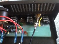
could it be the inputs are mis wired from the fuzzy picture i get the sense that a ground is connected to a hot and the two signal lines are across one jack???
so you now have jacks that are not isolated, as in grounded to chassis (no isolation washers)?
No. The jacks come with their own isolation washers - I do not use retrofitted jacks without them. However, I also tested the amp with the jacks removed from the case, and had them hanging out the back during tests - and it made no difference to the output.
in inspecting the input board did you use a magnifying glass? can't tell how many times that my own eyes deceived me when it comes to cracked solder joints.
I know the feeling! Hence I use a magnifying headpiece with an powered LED.
could it be the inputs are mis wired from the fuzzy picture i get the sense that a ground is connected to a hot and the two signal lines are across one jack???
I had considered that possibility. and checked the solder pads and traces to ensure that ground is in fact ground and speaker A and speaker B respectively.
Thanks for double checking on some things that are so easily overlooked.
just noticed you saying Mooly suggested removing a cap is there another thread about this?
No. Mooly has assisted me with another project so I PM'd him to confirm that this post is in the correct forum. He dropped the suggestion into that message after checking the schematics for me.
I decided to start with the power supply, and have now removed the 8200uf 80v power supply capacitors!
DVM measurement on both capacitors give readings fluctuating between 7,140uF to 9,700uF!!!!
Further tests of these caps using an ESR meter generated some interesting readings, with drops to 7,105uF and ESR =0.24ohms (where acceptable ESR=0.01ohms for capacitor of 8,200uf 80v!
Some reading of information on capacitor performance leads me to believe that these decreases and variations in capacitance, together with increased ESR could translate to fluctuation in power- translating to noise .....
Last edited:
ESR and capacitance meters are not always accurate when measuring such large caps. Measuring such low ESR values requires a four wire method to avoid measuring test lead resistance. If these caps would be faulty, both channels would hum.
Thank you for the comment and the reminder!
Yes, I did wonder about that myself - and I am aware that cleaning up the power supply may not fix the problem, however it will at least eliminate one of the variables!
Any information on how the 'four wire method' is implemented?
Yes, I did wonder about that myself - and I am aware that cleaning up the power supply may not fix the problem, however it will at least eliminate one of the variables!
Any information on how the 'four wire method' is implemented?
I'm sorry, I can't help you with that.
You mentioned that under certain circumstances one channel works and does not hum. Then the power supply is fine. Bad power supply capacitors would result in hum or buzz.
To fix the hum in the working channel: have you tried resoldering the connectors? Solder cracks can be invisible. Use a solder sucker or desoldering braid to remove the old solder and supply fresh rosin core solder.
Last edited:
- Status
- Not open for further replies.
- Home
- Live Sound
- PA Systems
- Biema W220 ll Channel hum