Hi!
I was wondering if there is a schematic out there for an audio peak indicator circuit that uses 1 multicolor (red/green) led that turns green under 0dbu, orange betwern 0dbu and +10dbu, and red above +10dbu. The trick here is to be able to turn off the green led gradually after 0dbu and completely off after +10dbu.
Any ideas? 🙂
Thanks!

How does the window comparator get the 'gradually' part right ? Isn't this an analogue application ?
Not exactly what you asked for, but here is rod elliott's 3 led level indicator:
http://sound-au.com/project244.htm
maybe you could adapt it for only 2 leds.
http://sound-au.com/project244.htm
maybe you could adapt it for only 2 leds.
Current cross-shifter, using a degenerated long-tailed pair with current source. You'll also need a level-sensing circuit that feeds the current shifter, of course.
A SSR to switch off green LED after +10dbu? 🤔
Just an idea tho, not tested.
https://www.digikey.com/en/products/detail/toshiba-semiconductor-and-storage/TLP4227G-F/1823620

Just an idea tho, not tested.
https://www.digikey.com/en/products/detail/toshiba-semiconductor-and-storage/TLP4227G-F/1823620
1. Find a talented circuit designer who will work for free, or for pizza and beer
2. Hand her this design specification
3. Victory!
edit- Don't be shocked if the final design happens to include a USD 0.75 microcontroller chip, to perform the logarithmic brightness-versus-current calculations. And maybe to also drive the LEDs using PWM.
_
2. Hand her this design specification
3. Victory!
edit- Don't be shocked if the final design happens to include a USD 0.75 microcontroller chip, to perform the logarithmic brightness-versus-current calculations. And maybe to also drive the LEDs using PWM.
_
Attachments
Also keep in mind that a gradually changing colour will be difficult to "read", since e.g. dark orange and red may be very similar. The advantage of defined thresholds is that levels are clearly distinguishable.gradually after 0dbu and completely off after +10dbu
For such a version to turn the green led on and off you could use two comparators (or op amps) that can source and sink current.
Both outputs low: green led off.
output 1 high, output 2 low: green led on
both outputs high: green led off.
That counts for substractive colours, like paint and printers: their primaries are magenta, yellow and cyan.green and red make brown, orange is made from yellow and red.
With additional colours, (primary) red, green and blue paint rules don't apply.
Red & green yields yellow, not brown.
Have you ever attended a theatre show?
More here.
Exactly.yields yellow, not brown.
I was not sure whether dimitri's comment was a joking one ...
You can build a forest of op-amps and comparators, or, like Mark suggested, a uP chip with a couple analog inputs can be programmed to drive as many LEDs as you like, however you want them to behave. These uP are dirt cheap and the only other thing you need is an audio rectifier. A fast uP could do that too. You probably need a driver chip for enough LED current.
An analog circuit would use a classic ladder chip(s) like LM3914 and add the color control to the anode drive. The anode drive switch over could be driven from the LM3914 outputs. An issue may be which LED lead is common, anode or cathode. You could adapt LM3914 to common anode LEDs with a positive driver chip or a bunch of PNP transistors but that's extra parts.
https://www.makerguides.com/interfacing-an-led-bar-graph-with-arduino-uno-a-complete-guide/
https://hiphopmakers.com/best-free-vu-meter-plugins
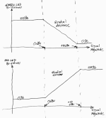
It depends on what kind of gradual you're expecting. You can certainly design a window comparator such that you get green for signals below X, red for signals above Y, and yellow(-ish), i.e., both red and green LEDs on for signals between X and Y. Sounds to me that that'll fit OP's application. It can also be built for a few bucks so it's cheap to try.How does the window comparator get the 'gradually' part right ? Isn't this an analogue application ?
Tom
Sadly TI is discontinuing those. It's currently on last time buy.An analog circuit would use a classic ladder chip(s) like LM3914
Tom
- Home
- Design & Build
- Electronic Design
- Bicolored LED Peak Indicator