I was experimenting with some components and I noticed that there is no need for biasing when I do this:

But there's a biasing problem when I move the resistor:

Why is this happening exactly? Can I really not implement any biasing or is there a problem with the software?
But there's a biasing problem when I move the resistor:
Why is this happening exactly? Can I really not implement any biasing or is there a problem with the software?
Not at all. You are enclosing the distortion-generating output stage within a negative feedback loop,
so it is less visible on your scope. But that is no way to design a good audio amplifier.
http://hifisonix.com/wordpress/wp-c...oss-Over-Distortion-in-Class-B-Amplifiers.pdf
so it is less visible on your scope. But that is no way to design a good audio amplifier.
http://hifisonix.com/wordpress/wp-c...oss-Over-Distortion-in-Class-B-Amplifiers.pdf
Last edited:
Not at all. You are enclosing the distortion-generating output stage within a negative feedback loop,
so it is less visible on your scope. But that is no way to design a good audio amplifier.
http://hifisonix.com/wordpress/wp-c...oss-Over-Distortion-in-Class-B-Amplifiers.pdf
Ah thank you! I think I understand what's going on now. I prefer a good differential to an OPAMP anyway but this seemed very interesting. I was expecting a distortion but there weren't. I was shocked. 😀
With the feedback connected to the speaker output node, look at the op amp output.
This output stage needs a single ended driver, plus a Vbe multiplier bias network.
This output stage needs a single ended driver, plus a Vbe multiplier bias network.
Last edited:
You need to measure the distortion, say via a .four directive, or look at the FFT of the output - the shape of a waveform on a oscillogram will not usually show visible distortion till its really gross (several percent even).
Careful biasing to reduce crossover distortion is essential to get good performance in this sort of circuit - plus the global feedback to reduce it even more.
With global feedback and without any biasing the are often instabilities too, leading to bursts of RF being generated on zero-crossings, another reason careful biasing is needed.
With the feedback connected to the speaker output node, look at the op amp output.
This output stage needs a single ended driver, plus a Vbe multiplier bias network.
Yes, I looked at the OPAMP output and there's definitely something wrong with it. Between -0.7 and +0.7 is distorted.
Actually I was experimenting with something like this because diode biasing simply doesn't work with >4-5W situations. But this does clip also. I don't know.

I wanted something simple to build on a prototype board but I'll probably go back to this and try to make it more simpler.

You need to measure the distortion, say via a .four directive, or look at the FFT of the output - the shape of a waveform on a oscillogram will not usually show visible distortion till its really gross (several percent even).
Careful biasing to reduce crossover distortion is essential to get good performance in this sort of circuit - plus the global feedback to reduce it even more.
With global feedback and without any biasing the are often instabilities too, leading to bursts of RF being generated on zero-crossings, another reason careful biasing is needed.
I actually did Fourier etc. but the results were decent, even at 20khz. But I didn't notice that I was stressing the OPAMP between -0.7 and 0.7. I think this can be a problem in real world scenarios.
Yes, I looked at the OPAMP output and there's definitely something wrong with it.
Between -0.7 and +0.7 is distorted.
The output stage distortion is still there, but the action of the loop feedback moves it to the op amp output,
which "predistorts" the signal so the speaker output looks better.
The loop feedback doesn't make the distortion vanish, rather it's hidden inside the loop.
Sort of like sweeping the dust under the rug.
Last edited:
Actually I was experimenting with something like this because diode biasing simply doesn't work with >4-5W situations. But this does clip also. I don't know.
Diodes can work. You would get less loading of the opamp
if the power transistors were driven by pre drivers.
Or basically use a Darlington. And then of course the Darlington's
having 20 to 30 ma of bias.
Far as using diodes with a opamp driver, everything would behave well
if you used constant current sources.
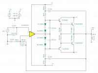
R4 , R5,C1 and R6 , R7, C2 are very basic bootstrap CCS
Below circuit in simulation is around 10/20 watts
and 1 kHz distortion @ .003 % and 20 kHz @ .03 %
Attachments
oopsie whoopsie
I had T1 the wrong way.
Fixed that and changed CCS values to 7K
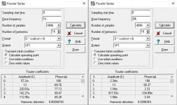
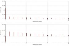
Included FFT distortion screen shoots
and overall Harmonic Profile
2nd Harmonic seems " Magical" lol
has strong second harmonic which I am sure those golden ears will hear
@ .002 % distortion

I had T1 the wrong way.
Fixed that and changed CCS values to 7K
Included FFT distortion screen shoots
and overall Harmonic Profile
2nd Harmonic seems " Magical" lol
has strong second harmonic which I am sure those golden ears will hear
@ .002 % distortion
Attachments

oopsie whoopsie
I had T1 the wrong way.
Fixed that and changed CCS values to 7K
Included FFT distortion screen shoots
and overall Harmonic Profile
2nd Harmonic seems " Magical" lol
has strong second harmonic which I am sure those golden ears will hear
@ .002 % distortion
Thank you! Usage of those capacitors are actually very smart and seems like this has been my problem. Very interesting. Although I'll try to bring down 10u values down a little. It doesn't feel right to use electrolytic in those places. I should go with polypropylene or tantalum except for C3.
Thank you! Usage of those capacitors are actually very smart and seems like this has been my problem. Very interesting. Although I'll try to bring down 10u values down a little. It doesn't feel right to use electrolytic in those places. I should go with polypropylene or tantalum except for C3.
Electrolytic are perfectly fine, and common for bootstrap current source.
Actually with all things simple there can be drawbacks. But that is the fun
of simple circuits.
But unfortunately the drawback to a bootstrap current source
is it has to maintain a constant voltage across the resistors.
The basic behavior which makes a current source.
That is the job of C1 and C2. they maintain constant voltage on R5,R6
from signal provided by the amplifier output.
Only problem is at low frequency there will be a phase shift
and there can ,... or will be distortion if the Capacitor values
are not large enough.
Same with C5, C6 if they are not large enough there will be distortion
at low frequency.
One thing I forgot to check. And C1 and C2 actually need to be
at least 47uf.
Ironically C5 , C6 also need to be around 47 uf for good low frequency
performance.
One thing I like is the simple approach and not have a million capacitor
values in a design. If possible.
So basically C1, C2, C3, C5 and C6 can all just simply be 47u
Electrolytic being perfectly normal and acceptable in all these locations.
2nd harmonic is not magical, its just perceptually masked better than other harmonics in single-tone situations. For multitone signals all distortions contribute to intermodulation products, which is bad news as they are not harmonically related, and thus not intrisically masked.
Consider for instance a 10kHz/11kHz dual tone - you don't want 1kHz intermod product appearing, and that's exactly what 2nd order distortion will create.
Consider for instance a 10kHz/11kHz dual tone - you don't want 1kHz intermod product appearing, and that's exactly what 2nd order distortion will create.
- Home
- Amplifiers
- Solid State
- Biasing of a Class AB amplifier isn't needed when it is used like this?