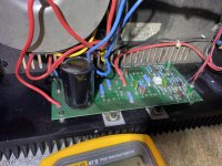
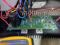
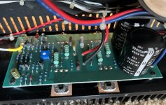
I picked up a N.E.W. class A amplifier that had a decent amount of damage to one of the boards. The actual board and traces were fine, there were just a few components that had become charcoal.
I replaced all of the components that were damaged and measured the components that were near them in circuit (transistors on a curve tracer, caps with a Peak ESR meter, etc) including the four output devices. Excluding the components that were charred everything measured normal. I then powered it up on a variac/DBT starting at about 50V. Got it up to line voltage, 122-124V and it doesn’t seem to really be drawing anyting, 0.02A and I’m guessing that’s from the LED that lights up on the front panel. Fuses are good obviously as the power LED lights up.
Measuring from ground I’ve got a +30Vdc and -30Vdc rail on each board directly from the bridge rectifier. Measuring the 3 pins on each of the outputs to the chassis, each pin has either a +30Vdc or a -30Vdc. Overall it seems to be a fairly simple design. I find it odd that only one board had damage, yet it seems that the entire amplifier is doing nothing. I’ve had this amp in the past and I remember it got quite warm, it’s been plugged in for at least 30 minutes and it’s still dead cold.
I’m hoping to get suggestions. I’ve worked on and have repairs several amplifiers so not a complete novice, but by no means an expert either. I have many tools and am competent enough that I should be able to do what is asked of me.
What is the best way of biasing a class A amplifier? Generally with A/B I’ll measure across the emitter resistors and set to a certain voltage (mV) if there isn’t available factory instruction.
Thank you,
Dan
Attachments
I think Mr. Pass designed this amp and it was made by Cary? Luckily Nelson frequents these forums.
Dan
Dan
What I can find is that this amp should be able to deliver 20Watt into 8 Ohm.
When this is correct and assuming that the full 20 Watt is in class A, bias current should be at least 2Amp.
And yes, the voltage caused by the bias can be measured on one emitter resistance, of course divided by the number of output transistors in parallel.
Hans
When this is correct and assuming that the full 20 Watt is in class A, bias current should be at least 2Amp.
And yes, the voltage caused by the bias can be measured on one emitter resistance, of course divided by the number of output transistors in parallel.
Hans
N.E.W. Ventura CD player
Hi. Might someone have a pointer to where I could find a schematic for the N.E.W. Ventura CD player? It is a hybrid design. Thanks. mike
Hi. Might someone have a pointer to where I could find a schematic for the N.E.W. Ventura CD player? It is a hybrid design. Thanks. mike
Measuring directly on the speaker connection points do you have 30VDC? If so the outputs have been shorted and need replaced. You don't happen to have a schematic for this anywhere do you?
I also picked up an A20 several years ago, and while it sounds good, it never quite sounded right. Boxed it up and put it in the closet with plans to eventually get around to "working" on it (maybe a re-cap since it's getting fairly old). My notes from before I boxed it up show I did notice some DC on the left channel. Right channel reads 0.003V DC and Left channel is 0.31V.
Decided to poke around the web for A20 info and found this thread.
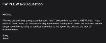
@saabracer23 - Have you tried reaching out to Cary yet to see what help they can offer? A service manual maybe? That was my next step. Also we must have slightly different iterations as I noticed some of the components in mine slightly differ.
Decided to poke around the web for A20 info and found this thread.
@saabracer23 - Have you tried reaching out to Cary yet to see what help they can offer? A service manual maybe? That was my next step. Also we must have slightly different iterations as I noticed some of the components in mine slightly differ.
Attachments
- Home
- Amplifiers
- Solid State
- Biasing N.E.W. A20.1 class A amplifier