as Papa sez, when making F2J :
pretty much the same applies for regular F2 ,regarding pot position
The F2's that I have updated with the JFETs need the
following changes:
R6 = 47k
C1 = 10 uF
Z1 removed
The potentiometer must be re-adjusted for minimum
distortion at 4.5 watts (symmetric clipping) and readjusted
after an hour.
The distortion results are typically a reduction from about 1%
at 1 watt to .25%.
pretty much the same applies for regular F2 ,regarding pot position
Zen Mod from post #51
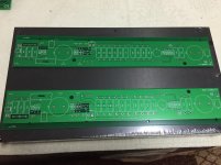
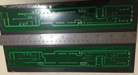
DIY F2 clone
adjust P1 to get a reading of one half, of the DC-supply voltage just in front of the outputcap! Connect your DVM to GND and in front of the outputcap and adjust P1 to get the correct reading.
DIY F2 clone
adjust P1 to get a reading of one half, of the DC-supply voltage just in front of the outputcap! Connect your DVM to GND and in front of the outputcap and adjust P1 to get the correct reading.
Attachments
that's if you don't have equipment to measure THD and/or to observe symmetrical clipping ..... or if you simply don't know how to do that
in any case half of DC supply voltage is starting point
in any case half of DC supply voltage is starting point
For F2j
DIY F2 clone
Measure at Drain pin (center) to ground point on schematic.
If bias is too low here <10v, I would replace pot with 10k, instead of 5k. Or replace R4 with a higher value.
DIY F2 clone
Measure at Drain pin (center) to ground point on schematic.
If bias is too low here <10v, I would replace pot with 10k, instead of 5k. Or replace R4 with a higher value.
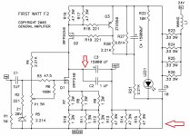
The end result you want is that the top CCS and the bottom part should present an equal resistance at ~ 2.8A such that they together burn ~ 67 watts.
And as the performance point we want is nicely enough at that point in the middle which is the red arrow with a dot in Zen Mods picture should have half the voltage of the rail. Or in short with 24V rails the half point should be 12V.
And as the performance point we want is nicely enough at that point in the middle which is the red arrow with a dot in Zen Mods picture should have half the voltage of the rail. Or in short with 24V rails the half point should be 12V.
How can achieve that end result?The end result you want is that the top CCS and the bottom part should present an equal resistance at ~ 2.8A such that they together burn ~ 67 watts.
How can achieve that end result?
first - knowing where to put black and red voltmeter probe
for basic things , there are already established and better places , than this , or any other (slightly advanced ?) electronic forum
for instance , here : Basic Car Audio Electronics
look at right side menu
for instance , here : Basic Car Audio Electronics
look at right side menu
I am trying to see if there is a shortcut rather than reading about the the whole website( will do it eventually).It should be something easy like put red prob at this point and black here kind of...
I know ZM does not want to give up that info, but someone else may.
I know ZM does not want to give up that info, but someone else may.
set your DVM to range of more than 20Vdc
connect black probe permanently for this test- with alligator clip anywhere on GND potential ....... say on Out+ wire or terminal
put red probe on positive side of +24V terminal (other one is GND) , write down exact voltage , let's call it Ub
now put red probe to mid pin of Q1 (be careful not to slip with probe , it's easy to make short ) or even better , with small alligator clip to C2-P. and fiddle with P1 to have voltage exactly of Ub/2
repeat the same for other channel
that's it
edit: going in electronics assembly without basic knowledge is almost as doing things blindfolded ; you need all the luck , or it will end in smoke and pain
Last edited:
Will assemble it over weekend. Yes I need a lot of luck.
Awaiting stuff from mouser and Antek. I ordered a 400Va 18V tranny. I was told 350 is what papa uses but 300 is too small.
Awaiting stuff from mouser and Antek. I ordered a 400Va 18V tranny. I was told 350 is what papa uses but 300 is too small.
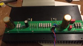
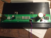
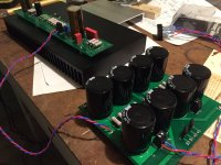
ZM, completed one channel,no smoke😀.Input Voltage 22.66V and Biased at 11.33V.Adjusted after 20 minutes to 11.12to 11.33V
Thanks for all your help.😀
Thanks for all your help.😀
Attachments
Last edited:
- Status
- Not open for further replies.
- Home
- Amplifiers
- Pass Labs
- Biasing F2 and F2J