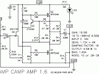
I bought a second aca kit, built and biased it same as the first 12.01-12.02V. Amazingly, if accidentally, precise. Wandering around inside the box, I measured the voltage at C1+, left and right, on both amps. The newer one, on both sides, is about .5v lower than the first.
Reasonable variation?
Curious coincidence that both sides of one amp are equally different from both sides of the other? Or is there a likely reason?
Would it be better if V at C1+ matched across all four boards?
Reasonable variation?
Curious coincidence that both sides of one amp are equally different from both sides of the other? Or is there a likely reason?
Would it be better if V at C1+ matched across all four boards?
Do you mean it has drifted over time? One likely reason is simply variation due to temperature. Check when hot and then cold and I would think you would see a significant difference (relatively speaking of course).
Slight differences in the midpoint voltage have no practical impact at all.
Slight differences in the midpoint voltage have no practical impact at all.
Let's have the schematic in-thread.
The "bias" sets Drain of Q1 to half of supply. You say this is the SAME on both builds?
The difference Q1-D to C1"+" is the drop across the low-value resistors, enforced by the very dependable threshold of Q3 (~0.6V) and the R8 R15 divider. I expect like 0.2V on each of the low-value resistors, a little more on two because higher value.
A 0.5V difference across R3R4 from one build to another just is not right.
Re-do your measurements.
Re-re-re-check locations and values and joint-quality of all parts. If you got R1R2-R3R4 or R8-R15 swopped, or Q3 turned-around, or Q3 a different pin-out.... too many possibilities to list.
Is anything running hotter on one build than the other? (The 20V may sting but is not fatal or short-term harmful to healthy adult humans; do take your rings off because the beefy supply can melt metal to the bone.)
Attachments
Last edited:
I understood it to be just the output DC at C1. If so, .5 is not much of an issue
and you can adjust the pot easily.
and you can adjust the pot easily.
- Status
- Not open for further replies.
