hi ,
i would like to make a modification to change my kt88 bias circuit to el34 bias circuit
assume i have made measurement in my amp with bias pot is adjusted to minimal and :
kt88 plugged to socket :
Vp88 = plate voltage
Iv88 = plate Current
Rc88 = cathode resistor
Vc88 = cathode voltage
el34 plugged to socket :
Vp34 = plate voltage
Iv34 = plate Current
Rc34 = cathode resistor
Vc34 = cathode voltage
Will replacing Rc88 with the right Rc34 value do the mod done ?
How can i get the value of Rc34 from the other variable .
Thanks in advance
Do you have a schematic that you can post? EL34's typically need less plate voltage and less bias voltage for proper operation. There are also different requirements for grid leak R but I think that the KT88 requirement is more stringent than the EL34 requirement.
EL34's typically need around 35V +/- or so for bias voltage; depending on the design, the existing bias pot may have enough span to get you there. It's easy enough to measure. If not you'll have to change an R value in the bias circuit.
Can you measure & post your existing plate voltage and the voltages at each end of the bias pot range? Remove the output tubes when measuring the min bias voltage.
In in typical fixed bias arrangement the cathode R is only used to measure bias current.
Also keep in mind that an EL34 is rated for around 24W and the KT88 is rated at about 42W dissipation. So your Vplate X Iplate = power dissipated needs to be less depending on how hard you are driving the KT88's now.
Last edited:
Hi ..
with the output tube removed
the plate voltage is 460 v ,
the (4) bias pot voltage is 0 .
grid resistor is 1 k , feed bias resistor is 120k
i notice (2) 10 ohm 2 watt resistor ,
(2) 46k resistor and (1) 22k near the bias pot .
this bias circuit is used for 2 output tube(s) .
Please Advise ,
Thanks .
So the minimum bias voltage is zero? What's the max bias voltage?
What is the value of the cathode R?
What nominal bias current have you been using with the KT88's?
What is the value of the cathode R?
What nominal bias current have you been using with the KT88's?
Last edited:
Hi ,
bias voltage is 0.38 vdc ,
nominal bias current is 26 mA ,
cathode resistor is 1k ohm
please advise ,
thanks for your response
bias voltage is 0.38 vdc ,
nominal bias current is 26 mA ,
cathode resistor is 1k ohm
please advise ,
thanks for your response
I'm no expert but now you have me confused.......the cathode R's seem very high for fixed bias..................they are usually 1 ohm or 10 ohms for fixed bias, something convenient to measure voltage across to calculate current.
26ma seems way low for KT88 current also..........
Also, your bias voltage is very low; it should be somewhere in the range of 35-55VDC or so.
typical fixed bias operating conditions for EL34's are 400VDC@60ma (around -35VVDC bias or so), this equals 24W dissipation.
typical fixed bias operating conditions for KT88's are 500VDC@80ma, which is about 40W dissipation.
I wouldn't suppose that you have a schematic that you can post?
When you have the bias adjusted properly, what voltage reading are you getting? With the amp up and running properly, what is the DC voltage at pin 5 of the KT88's at idle?
What is the DC voltage drop across the cathode R's?
Hi boywonder ,
you're right i was wrong .
the cathode resistor is actualy 10 ohm , where 1k resistor is grid leak resistor .
bias voltage and current was measured in bias trim pot (0.35vdc , 26.8 mA)
did you mean measuring power tube anode (pin 3 ) voltage and current for
--> fixed bias operating conditions for KT88's are 500VDC@80ma ?
i'll should give you this value tomorrow as i'm out of town today -> dc voltage at pin 5 kt88 idle and dc voltage drop across cathode rs
thanks so much
Also, very carefully (use clip leads if you have them, or use one hand and put the other in your pocket) measure the anode voltage of the KT88's at idle. (pin 3 to ground).
Do you already have EL34's?
Do you already have EL34's?
You must use Ua/Ia curves to find out! Ie you should draw the loadlines. Nothing else is worth using.
hi ,
i got 400vdc on pin 3 (plate)
and 0.35 vdc on pin 8 (cathode)
can't get current reading in both of them , why is that ?
thanks .
i got 400vdc on pin 3 (plate)
and 0.35 vdc on pin 8 (cathode)
can't get current reading in both of them , why is that ?
thanks .
By "current reading" do you mean that you are trying to use your meter in a current (milli-amps/amperage) mode? Don't do that. Measure only voltages and use ohms law to determine current where needed.
Does the bias control adjust the DC voltage to the grids or does it adjust the DC resistance in the cathode circuit?
Does the bias control adjust the DC voltage to the grids or does it adjust the DC resistance in the cathode circuit?
What's the DC voltage at pin 5 of the KT88's and the voltage drop across the cathode R at idle?
The DC voltage at pin 5 is your bias voltage.
As mentioned, you want to use your voltmeter to measure currents, using ohms law. Measure voltage across the cathode R and use ohms law to calculate current. I=E/R
The DC voltage at pin 5 is your bias voltage.
As mentioned, you want to use your voltmeter to measure currents, using ohms law. Measure voltage across the cathode R and use ohms law to calculate current. I=E/R
Hi ,
i got -50 vdc on pin 5 and 0.35 vdc on pin 8 (the same as bias pot voltage).
i think bias control adjust the DC voltage to the grids ,
is there any way to make sure ?
Thanks very much for u're help
i got -50 vdc on pin 5 and 0.35 vdc on pin 8 (the same as bias pot voltage).
i think bias control adjust the DC voltage to the grids ,
is there any way to make sure ?
Thanks very much for u're help
Great, sounds like your KT88's are running at 400V, 35ma........which is just loafing along at 14W dissipation, and way under biased.
Do you know what the target operating point is for your amp? Do you know if the amp is wired in ultralinear or triode?
Look at the application data here TDSL Tube data [KT88] for typical KT88 operating conditions.
The data is for cathode bias, in fixed bias the B+ needs to be a little less than shown to keep the dissipation within limits.
You may want to bump up your bias current to 70-80-90 ma and see if you like the sound of the KT88's.
Do you have the EL34's already?
Hi ,
the amp is wired in triode mode ,
i already order el34 , will come in a week .
have borrowed my friend's el34's try biasing but can't get voltage reading in bias pot ,
why is that ?
which resistor i should change in bias circuit ?
cathode or grid resistor ?
Thanks.
the amp is wired in triode mode ,
i already order el34 , will come in a week .
have borrowed my friend's el34's try biasing but can't get voltage reading in bias pot ,
why is that ?
which resistor i should change in bias circuit ?
cathode or grid resistor ?
Thanks.
Hi ,
can't get voltage reading in bias pot ,
why is that ?
Thanks.
We need further definition of the problem......what you may see is that you run out of pot adjustment before obtaining enough bias current for the EL34's. This will require possibly changing a resistor value in the bias circuit. You will not need to change the cathode R, it's only purpose in life is to allow proper bias current measurement by measuring the voltage across it.
Have you been successful at getting your existing KT88's properly biased?
Another question that I forgot to ask earlier....do you have two bias pots? ie one for each output pair?
You need to adjust the bias pot to get around .5V across each cathode R; this is 50ma current (across a 10 ohm cathode R), a reasonable place to start with EL34's @ 400V anode V. This should require somewhere around -30 to -35VDC bias voltage on pin 5.
hi ,
yes it does have two bias pot , one for each output pair .
in the amp manual , it's said that the amp is biased between min 0.35vdc(35ma)
and max 0.40vdc(40mA) . i'm now biasing it to 0.40vdc . is it ok to bias the tube exceed the amp manual ?
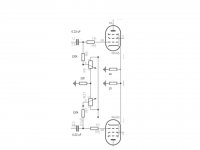
in the bias pot i notice (2) 1k r (rgSeries) , (2) 120k r (rgParallel), (2) 0.22uF cap , 2 10 r(rCathode) , and (1) 22k r .
do you have any idea what this 22k resistor is ? i'm trying to figure it out.
the amp is wired in triode mode using 1k resistor in 47k resistor .
cheers ..
yes it does have two bias pot , one for each output pair .
in the amp manual , it's said that the amp is biased between min 0.35vdc(35ma)
and max 0.40vdc(40mA) . i'm now biasing it to 0.40vdc . is it ok to bias the tube exceed the amp manual ?
in the bias pot i notice (2) 1k r (rgSeries) , (2) 120k r (rgParallel), (2) 0.22uF cap , 2 10 r(rCathode) , and (1) 22k r .
do you have any idea what this 22k resistor is ? i'm trying to figure it out.
the amp is wired in triode mode using 1k resistor in 47k resistor .
cheers ..
So with the EL34's installed, you ran out of bias adjustment before you could get .35V/35ma-.40V/45ma??
Can you draw/post a diagram of the bias circuit?
Can you draw/post a diagram of the bias circuit?
- Status
- Not open for further replies.
- Home
- Amplifiers
- Tubes / Valves
- Bias Circuit Calculation