Morgan Jones wrote of the BH curve stressing quiescent currents "straighten out" this kink.....from magnetic stiction.
Question is.... if you have an SE running 2.2 watts of output power and your choices are a 6W OPT and an 11W OPT, does the higher mass unit need a higher quiescent current, such as... the low power does not have enough current to straighten out this kink?
Is there a rule of thumb as to power output to power capacity (Of OPTs')....& overkill ratios are counterproductive?
_____________________________________________________Rick......
Magnetic Zero Crossing AKA B-H Kink?
I have not been able to verify the existence of a kink in the middle of a B-H loop as shown in the MJ book (1). It is however easily verified that there is reduced primary inductance at small signal levels (1,2).
I have looked into this kink and the related notion of magnetic zero crossing, and found 2 additional sources describing this "kink", both of which are "penciled-in" curves and not actual measurements. Eddie Vaughn (3) shows a dotted line kinked curve as a "perfect" material curve without hysteresis but gives no reason or theory behind it. In Sound Practices Spring 1994, Dr. Tom Hodgson (4) shows various minor B-H loops of different magnitudes, with a ficticious kinked dotted line drawn through the various minor loops.
I find no theoretical reason in Faraday's law to explain this kink, as the actual flux reversal and hence "stiction" effects should occur at the *ends* of the B-H loop, not in the middle.
I would be very interested if someone could enlighten me as to the nature of this kink and how I could make a measurement (B-H trace) that shows it.
Cheers,
Michael
(1) Valve Amplifiers, third edition, Morgan Jones 2003,Fig. 6.3 and related text p. 382
(2) Low Level Audio Signal Transfer Through Transformers Conflicts With Permeability Behavior Inside Their Cores, Menno Van Der Veen, AES 2007
(3) Single Ended vs. Push Pull: The Deep Dark Secrets of Output Transformers, Eddie Vaughn Monograph, p.4 Fig. 4
(4) Single Ended Amplifiers, Feedback, and Horns: Some History, Dr Tom Hodgson, Sound Practices Spring 1994, Fig. 3 p.40
Morgan Jones wrote of the BH curve stressing quiescent currents "straighten out" this kink.....from magnetic stiction.
Question is.... if you have an SE running 2.2 watts of output power and your choices are a 6W OPT and an 11W OPT, does the higher mass unit need a higher quiescent current, such as... the low power does not have enough current to straighten out this kink?
Is there a rule of thumb as to power output to power capacity (Of OPTs')....& overkill ratios are counterproductive?
_____________________________________________________Rick......
I have not been able to verify the existence of a kink in the middle of a B-H loop as shown in the MJ book (1). It is however easily verified that there is reduced primary inductance at small signal levels (1,2).
I have looked into this kink and the related notion of magnetic zero crossing, and found 2 additional sources describing this "kink", both of which are "penciled-in" curves and not actual measurements. Eddie Vaughn (3) shows a dotted line kinked curve as a "perfect" material curve without hysteresis but gives no reason or theory behind it. In Sound Practices Spring 1994, Dr. Tom Hodgson (4) shows various minor B-H loops of different magnitudes, with a ficticious kinked dotted line drawn through the various minor loops.
I find no theoretical reason in Faraday's law to explain this kink, as the actual flux reversal and hence "stiction" effects should occur at the *ends* of the B-H loop, not in the middle.
I would be very interested if someone could enlighten me as to the nature of this kink and how I could make a measurement (B-H trace) that shows it.
Cheers,
Michael
(1) Valve Amplifiers, third edition, Morgan Jones 2003,Fig. 6.3 and related text p. 382
(2) Low Level Audio Signal Transfer Through Transformers Conflicts With Permeability Behavior Inside Their Cores, Menno Van Der Veen, AES 2007
(3) Single Ended vs. Push Pull: The Deep Dark Secrets of Output Transformers, Eddie Vaughn Monograph, p.4 Fig. 4
(4) Single Ended Amplifiers, Feedback, and Horns: Some History, Dr Tom Hodgson, Sound Practices Spring 1994, Fig. 3 p.40
The B-H curve relates total current around the core (i.e., magnetization) to the flux, and by dPhi/dt, the EMF, in the core.
As such, aaaaaaany thought of magnetic behavior at all, only applies where inductive reactance is relatively significant. This means LF cutoff.
To be perfectly clear, the B-H curve has absolutely no bearing whatsoever on the midband or HF performance of your amplifier. You can completely ignore it.
To understand what the B-H curve is, you have to understand magnetics. If you connect a transformer to a constant voltage supply, and measure current, current will rise according to V = L*dI/dt. Eventually, current will reach saturation, at which point flux isn't rising further, so EMF drops towards zero. This can be measured by a secondary winding, since resistive drop in the primary usually causes a significant error in this measurement. (Without EMF to cancel the applied voltage, current starts shooting way up, and source and primary winding resistances will eventually limit current.) When the transformer reaches saturation, secondary voltage falls to zero. So the overall effect is, apply current, and you see a pulse at the output, then it stops when it reaches saturation. The area of this pulse is how much flux the core can handle, in Webers (1Wb = 1V*s), which is directly the amount of voltage the transformer can pass at a given frequency (Wb = Vpk/2*pi*F for a sinusoid).
Some materials, like iron, have more nuanced B-H curves. Initial permeability is relatively low, so inductance at low signal currents is relatively low and therefore the magnetizing current (which, remember, is insignificant compared to the load at most frequencies) is relatively high. As the signal grows, the current becomes relatively lower (but does not actually drop, because magnetizing current must always be increasing during a half cycle). As saturation approaches, current goes up again, on the peaks.
The only condition for an amplifier where this is significant is at low frequencies. This is pretty easy to observe in a PP amp when the output impedance is high (including source impedance -- triodes or pentodes with little or no NFB). Under this condition, when the output is overdriven (don't worry about generating peak voltages, that's just silly -- do worry about melting screen grids, however!), you get something resembling a square wave, that kind of droops as time goes on. This is due to the magnetizing current dragging down the voltage. The rate at which it droops is a window into the transformer's B-H curve. For really low frequencies, the droop somewhat suddenly stops altogether, dropping to zero -- this is saturation (and, note your tubes are now driving a near short circuit, so they'll be getting warmer under this condition).
Tim
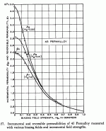
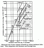
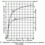
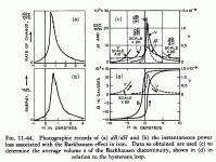
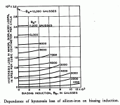
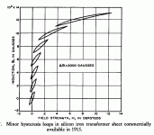
Some real data from Bozorth "Ferromagnetism" (the Bible on magnetics, all Ferro.. books refer back to this one)
Since the question referred to size of xfmr effects. A comparison of xfmr A with 1X core and xfmr B with 2X core area is in order.
Assuming same inductance, and related Zpri, Zsec and turns ratio for both cores and same voltage drive on the primary. Xfmr B will have .707 times as many turns to get the same inductances and related Zpri, Zsec. So flux density for core B will be 1.414/2 = .707 of core A. Core loss per volume scales at approx. 1.6 power of flux, so (.707)^1.6 = .574 However, core B has more volume, (1.414)^3 = 2.827 giving .574 * 2.827 = 1.62 times the core loss of core A. Eddy currents come out a little better since they scale as 2 power of flux. So a 1st estimate would be that the larger xfmr B has more losses than the smaller one for the same signal.
However, the larger core will have larger wire, so less copper loss too. With the bigger winding window we can go further and request an xfmr with higher inductance (more turns) for core B and still handle the same power as the smaller one. This would be equivalent to asking for a higher primary and secondary Z spec. So if we request the same number of turns on both core A and core B, the Z and inductance ratings for core B will be (1.414)^2 = 2X. Recalculating the the core losses: (.5)^1.6 = .33 and the volume is still 2.827 X giving .33*2.827 = .93 the loss of core A. So if you do it right, a larger xfmr will have less loss than a smaller one for the same power.
Not only is the loss reduced, but the larger core has 2X the flux headroom, so odd harmonic distortion from saturation will be greatly reduced at max signal. Reduction of the hysteretic core loss reduces even harmonic distortion also (for SE case, see 5th and 6th charts, P-P case does not have even harmonic dist.). And the extra inductance (2X) will greatly reduce magnetizing current induced distortion from the tubes.
And finally, every magnetics book published will tell you, for the ultimate in low distortion, get rid of the DC current from SE operation. SE operation causes assymetric hysteresis causing even harmonic distortion, it gives you half the flux headroom to avoid odd harmonic distortion, and it gives you abysmal permeability or inductance to avoid magnetizing current. And finally, there is no crossover distortion in P-P operation of an xfmr. Take a look at graph 3 and you will see hysteresis drops faster than flux at low flux. Transformer operation becomes very linear when operating in the initial flux region (no Barkhausen avalanching), although permeability and hence magnetizing current will be relatively greater there.
Attachments
Last edited:
Dear God I just love this stuff!
My math extends up to but no further than Differential Calculus(sp?) I can just eat this up!
I will have to study up on such things as Oersteds & Barkenhausen?
Perhaps I shall steer my way toward a field of study now. An embarkation...."more books please!"
In an association with a fellow DIYr' & Argentinian "Mosquito" I am building my first tube amp(The fleabreeze)....chassis selected & funds allocated...
I must now peruse thru Amazon.com to find some more reading material... I have a lot to learn now.
_________________________________________________Rick.....
edit for above:
That last sentence should read:
Transformer operation becomes very linear when operating in the initial permeability region/ low flux region (little or no Barkhausen avalanching, see chart 4d, and notice the Barkhausen peak occurs right where SE biasing centers on), although reduced permeability and hence relatively (to the small signal) greater magnetizing current will occur near zero crossing. Magnetizing current is never-the-less still smaller at the zero crossing than at larger fluxes.
Last edited:
- Status
- Not open for further replies.
