Hi Everyone,
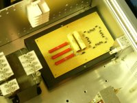
I just picked up a pair of Model 2SW1's that are going to need some work. The panels look ok and I've examined them and no burns , flapping or peeling of the aluminized mylar.
The amps have been muddled. So much work is needed. Can anyone say what type of diodes are required in the voltage multiplier PIV and current?
Thanks.
Attachments
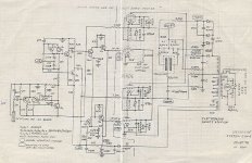
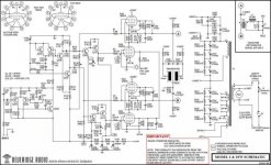
By the schematics, voltage rating should be more than 4kV, 1A, to be safe. Avalanche type perhaps. Standard recovery.
Thanks, I think in this application the diodes are in a doubler arrangement and each one sees 1/2 the voltage.
1A diodes are scarce in this form factor all are 200 -250 mA. Given the physical size of the original diodes with the the DO41 pkg. and the timeframe they were built. I doubt they are more than 200mA. forward current.
The specification of M40 on the diode and schematics has been elusive. I can't find any reference to that part number anywhere- even in my 1978 Motorola catalog.
Someone subbed some NTE 1.5kV diodes in one amp and of course- those went south.
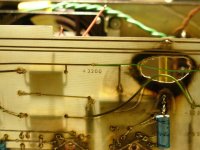
Nevertheless, I am going to series connect a pair of 4KV 250 mA diodes with a 470K load sharing resistor for each position- Hoping for the best!
1A diodes are scarce in this form factor all are 200 -250 mA. Given the physical size of the original diodes with the the DO41 pkg. and the timeframe they were built. I doubt they are more than 200mA. forward current.
The specification of M40 on the diode and schematics has been elusive. I can't find any reference to that part number anywhere- even in my 1978 Motorola catalog.
Someone subbed some NTE 1.5kV diodes in one amp and of course- those went south.
Nevertheless, I am going to series connect a pair of 4KV 250 mA diodes with a 470K load sharing resistor for each position- Hoping for the best!
For the voltage doubler in the GM70 amps I wanted to use the least amount of components, so I ordered the 6kV diodes, which, looking at the data, are probably just 6 (or more) series connected diodes in a single package. I am happy with them.
https://www.tme.eu/en/details/by6-dio/tht-universal-diodes/diotec-semiconductor/by6/
https://www.tme.eu/en/details/by6-dio/tht-universal-diodes/diotec-semiconductor/by6/

470K load sharing resistor
Connecting diodes in series causes their forward voltage to add which I want . You should parallel each diode with a high value resistor - maybe 470KΩ. Without this, the reverse voltage won’t be evenly distributed across each diode because the leakage current isn't equal -even same diode same batch. If that happens some of the diodes will have a higher PIV than will the others. It may well be enough to make the diode breakdown which would cascade to the other diodes- and destruct. So good practice to add a load sharing resistor to series connected diodes. That's why I do it. Nothing to do with the series HV caps.
????
This because of the series connected electrolytic capacitors...
Connecting diodes in series causes their forward voltage to add which I want . You should parallel each diode with a high value resistor - maybe 470KΩ. Without this, the reverse voltage won’t be evenly distributed across each diode because the leakage current isn't equal -even same diode same batch. If that happens some of the diodes will have a higher PIV than will the others. It may well be enough to make the diode breakdown which would cascade to the other diodes- and destruct. So good practice to add a load sharing resistor to series connected diodes. That's why I do it. Nothing to do with the series HV caps.
Thank you that is a good option,,, it is universally unavailable until September- it is a much larger form factor than original at 1A - but I could of made this work. I had to series string two 4 kV diodes together for good measure.For the voltage doubler in the GM70 amps I wanted to use the least amount of components, so I ordered the 6kV diodes, which, looking at the data, are probably just 6 (or more) series connected diodes in a single package. I am happy with them.
https://www.tme.eu/en/details/by6-dio/tht-universal-diodes/diotec-semiconductor/by6/
Now the intent is more than obvious, which was not clear initially. I would suggest so-called avalanche diodes, which do not need shunts per say. Such as BYT62 BY228 BY448 BYX82, BYX83, BYX84, BYX85, BYX86 etc.Connecting diodes in series causes their forward voltage to add which I want
Alex
I'm worried about these 200MA parts!
A tube shorting can easily exceed that and will fail your HV string. And a failed HV string is the perfect way to fail your transformer.
Here's what I did: For each original diode I used three BY228 in series, with 10M 1/4W balancing resistors added. They look terrible and don't fit the board well but hey they work and I don't worry about them anymore. I did this way back when I first did my rebuild and it has calmly survived many tube failures.
I use multiple 1N4007 diodes in series, never had any issue (amps working for more then 15 years already). As i replaced my transformers a diode bridge is used instead of a voltage doubler circuit.
Anyway, in the original Bevs there is a 200 Ohm resistor in series with the tubes that will burn in case a tube will short. That is why it should be placed way above the circuit board...
Anyway, in the original Bevs there is a 200 Ohm resistor in series with the tubes that will burn in case a tube will short. That is why it should be placed way above the circuit board...
Attachments
- Home
- Loudspeakers
- Planars & Exotics
- Beveridge OTL amp