Hello, I wonder if I could ask for some help please.
I have an Arcam 5+ and want to make sure that I put the clock into the right position on the board, including its ground. The board is the pfm flea with Tent clock which has two outputs each with a small smd resistor.
I believe I need to have the output divided by two? I dont fully understand where I can do this. My 7220 chip has been removed btw. (I'm convinced I made a mistake before so want to start fresh)
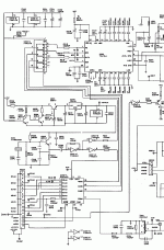
Attached is part of the schematic which is where the clock and lines are routed. Any explanation of it would be much appreciated.
And the questions are:
1) Does the 11.xxxmhz clock have to be divided by two (or more?)
2) where best to insert the two clock output. I thought one direct to the receiver at the connector, but the other?
3) Do I have to ground the flea onto the audio board, and where? (it has its own transformer,bridge,cap - the flea has reg)
4) What do the two chips do that Arcam used on the 5+. For example, im confused to what the not gates on the first chip do.
5) Could I implement DEM with small mods?
Thank you very much, Brian.
Attachments
brianuk said:Hello, I wonder if I could ask for some help please.
I have an Arcam 5+ and want to make sure that I put the clock into the right position on the board, including its ground. The board is the pfm flea with Tent clock which has two outputs each with a small smd resistor.
I believe I need to have the output divided by two? I dont fully understand where I can do this. My 7220 chip has been removed btw. (I'm convinced I made a mistake before so want to start fresh)
Attached is part of the schematic which is where the clock and lines are routed. Any explanation of it would be much appreciated.
And the questions are:
1) Does the 11.xxxmhz clock have to be divided by two (or more?)
2) where best to insert the two clock output. I thought one direct to the receiver at the connector, but the other?
3) Do I have to ground the flea onto the audio board, and where? (it has its own transformer,bridge,cap - the flea has reg)
4) What do the two chips do that Arcam used on the 5+. For example, im confused to what the not gates on the first chip do.
5) Could I implement DEM with small mods?
Thank you very much, Brian.
Hi
Answers are
1) No, the original clock is also 11.2896 MHz
2) The original clock is buffered by 2 HC04 inverters, best to lift the series resistors t their outputs and insert new clock there. Connect clock ground close to this point
3) The flea **** can run without ground, the DC current required runs through the clock ground
4) They use reclcocking between the 7220 and the 1541 - well done ! Keep in place
5) What is DEM ?
Hi Mr Tent, I guess you are qualified to answer ! 😀 thanks.
DEM is a kind of reclocking I believe but also involves connecting to the pins of the TDA1541 where a 680pf cap would be only? Oscillator?
My 7220 is gone a long time ago and is now NOS.
I thought the TDA1541 cant have 11.xxx mhz as a clock, which led me to here, I was convinced this was my error and i needed a 1/2 clock to the TDA1541.
I'll have to redraw the schematic showing the flea in place, thanks
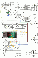
Colour coded schematic with Flea
Hi Guido,
I have added the flea and shown where I think you mean to connect it up.
1) Is this correct?
2) It looks like the HC04 is no longer used so it and associated components can be removed? Just leaving 175 to do reclock?
3) The compoents in blue box (resistor and cap), should I remove them?
Thanks.
Attachments
Re: Re: Best place to put clock on Arcam 5+ please.
Hi Guido and Brian
Would it be better (but more complicated) to directly clock the TDA1541 with a divided clock from the Flea (as the standard reclocking of the bitclock shares the 74HC175 with reclocking of WS and Data)? It would mean building a separate board with a clock dividing circuit to feed the Dac chip.
DEM = Dynamic Element Matching. DEM reclocking involves removal of the 680pf capacitor on pins 16 an 17 of TDA1541 (C223) and replacing it with a purpose biult clocking circuit...as proposed by Henk ten Pierick.
Guido Tent said:
Hi
Answers are
4) They use reclcocking between the 7220 and the 1541 - well done ! Keep in place
5) What is DEM ?
Hi Guido and Brian
Would it be better (but more complicated) to directly clock the TDA1541 with a divided clock from the Flea (as the standard reclocking of the bitclock shares the 74HC175 with reclocking of WS and Data)? It would mean building a separate board with a clock dividing circuit to feed the Dac chip.
DEM = Dynamic Element Matching. DEM reclocking involves removal of the 680pf capacitor on pins 16 an 17 of TDA1541 (C223) and replacing it with a purpose biult clocking circuit...as proposed by Henk ten Pierick.
- Status
- Not open for further replies.

