Hello,
I would like to know how efficient the presented scheme is in terms of ripple rejection.
Thank you.

I would like to know how efficient the presented scheme is in terms of ripple rejection.
Thank you.
Last edited:
Much of this information can be deduced from the data sheet. Decoupling of the adjust pin plays a big part and 10uF is reckoned to be as large as you need to go and togather with an optimal layout (and that is most important) could be around 80db. I don't think 220uH would do anything in reducing input ripple, you need magnitudes more inductance than. In fact a low value inductance could cause significant ringing as the diodes come into and out of conduction.

I'm more concerned about the polarity of the smoothing caps on the negative side and the direction of the diodes over the regulators...
secondly, full wave rectification will reduce it by at least half for the cost of two more diodes.
First...read the data sheet for the devices you use...nobody can give better advice on proper use than the designer. Next...Using a transformer with only one secondary is the greatest error here...use a good quality center-tapped or dual secondary transformer so a full wave rectifier can be utilized instead of the half wave rectifier you show, that will reduce the ripple presented to the regulators in half, making life easier for them. It is also a good idea to put a .1uF ceramic cap from as close to the input pin as possible to ground for circuit stability. The next thing is get rid of the inductors and put those one ohm resistors there instead, and delete the third pair of 2200uF caps, they are over-kill that could actually be detrimental to the goal of reducing noise and ripple, and "C-adj" doesn't need to be that large, the law of diminishing returns says that 10uF to 20uF is usually plenty. Also be aware that the pin-outs of the LM317 and the LM337 are different...don't ask me how I learned that forty some years ago!
Mike
Mike
Last edited:
I need to make a symmetrical power supply using only one secondary of the transformer.
I understood what are the problems of the scheme I presented.... Do you have other tips?
I understood what are the problems of the scheme I presented.... Do you have other tips?
Neither you nor I can break the rules of physics...no matter how convenient it would be. Using a single secondary transformer is the biggest factor causing ripple to begin with. Maybe this will help...
PSU Designer
Mike
PSU Designer
Mike
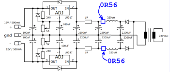
1. You've drawn a couple of protection diodes incorrectly (backwards). Double check the original schematics, from which you copied these circuits.
2. For the sake of overall hygiene and resonant damping, you could think about installing 0.56 ohm resistors in series with the two inductors, as shown in blue below.
3. Do a blackboard calculation (or a software circuit simulation) to find out which frequencies your inductors affect -- and which frequencies they don't affect. Are you happy with this result?
4. Maybe you just want to use the VRDN regulator project instead. VRDN can accept either a single-secondary, or a dual-secondary transformer. Plenty of diyAudio members have already built it, and are happy with the results. (VRDN link)
_
Attachments
I need to make a symmetrical power supply using only one secondary of the transformer.
I understood what are the problems of the scheme I presented.... Do you have other tips?
The premise is wrong, you have to use a transformer with two secondaries for good performance.
Come on, so what if you start with a bit more ripple? I frequently use wallwarts with AC output for symmetrical supplies.
"Come on, so what if you start with a bit more ripple? I frequently use wallwarts with AC output for symmetrical supplies."
But it is the largest factor that will contribute to the problem at hand, and it's not merely a bit more ripple, it's more like double the ripple...no sense in doing it the hard way.
Mike
But it is the largest factor that will contribute to the problem at hand, and it's not merely a bit more ripple, it's more like double the ripple...no sense in doing it the hard way.
Mike
Double the ripple by refilling the caps once per mains cycle instead of twice --> +6dB (increase in ripple)
LM317 ripple reduction --> -65dB (decrease in ripple). They're so proud of this, they plot it on the datasheet.
LM317 is the largest factor.
LM317 ripple reduction --> -65dB (decrease in ripple). They're so proud of this, they plot it on the datasheet.
LM317 is the largest factor.
If the transformer has two identical secondaries (many or most do nowadays), use them. Have one go to a full wave bridge, to filter cap(s), to a regulator. Duplicate the exact circuit on the other secondary. Connect the + output of one to the - output of the other. You now have a +/- supply that uses the same parts in each half.
If there were two secondaries, you could just connect the secondary windings in series, ground the midpoint and connect the ends to one bridge rectifier.
Thank you for the explanations. I will choose another project for my needs.The premise is wrong,.....
The correct way to design a power supply is to consider the overall system requirements rather than just one aspect, i.e., ripple. You should always design a power supply for the maximum ripple the system can tolerate while still meeting specifications for the overall response. I know this seems counterintuitive and goes against the grain of "everything the best," but it is an engineering reality. One problem often overlooked is the peak ripple current flowing through the transformer windings, rectifier diodes, and filter capacitors. It is inescapable that in a simple diode capacitor power supply, the price of decreasing voltage ripple via using larger capacitors is an increase in the magnitude of current peaks. The ratio of peak current in the transformer to average DC current delivered can be quite high, even with moderately sized capacitors - I have seen designs that go well over a 10:1 ratio! The current peaks resemble a triangular shape and can also be quite high in harmonic content. I will endeavor later today or tomorrow to attach a white paper I wrote on the topic.
Make sure your white paper includes the effects of resistance in the transformer primary circuit, resistance in the transformer secondary circuit, resistance of the rectifier diodes themselves (Spice diode model parameter "Rs" ), filter capacitor internal resistance ("ESR"), and the designer's option to install/omit additional series resistors into the current path from secondary to first filter capacitor.
The transformer windings are not zero ohms, the mains fuse is not zero ohms, the IEC common mode choke / integrated filter is not zero ohms, the diodes are not ideal, the capacitors are not ideal. And the designer might choose to install a wee tad ooch of series resistance if she's worried about component stress.
The transformer windings are not zero ohms, the mains fuse is not zero ohms, the IEC common mode choke / integrated filter is not zero ohms, the diodes are not ideal, the capacitors are not ideal. And the designer might choose to install a wee tad ooch of series resistance if she's worried about component stress.
- Home
- Amplifiers
- Power Supplies
- Beginner's question about the LM317/337 schematic