I've seen some references online regarding the use of Schottky diodes as a Baxandall diode in quasi designs.
All were saying to use classical silicon diodes or transdiodes.
In my design Schottky diodes gave the best overall THD in LTSpice.
I've seen a reference like "Schottky diodes defeat the purpose" as Baxandall diodes.
It happens that I've read this after I've install a BAT41 Schottky diode in my quasi design.
So, should I change it to a normal Si diode or transdiode?
Also, why do Schottky diodes model best in LTSpice with a quasi output?
I would have thought the schottky diode would have better recovery at higher frequencies and volumes.
The Baxandall diode increases the gain of the driver, however, I found this also increased the risk of oscillation and I had to put a capacitor across the driver BC.
The Baxandall diode increases the gain of the driver, however, I found this also increased the risk of oscillation and I had to put a capacitor across the driver BC.
I had oscillations but I just had to add a 10uF capacitor across the gates of the drivers. That stabilized the amp. Drivers don't have any cap across the driver.
Although the original driver did have 500pF across bc
Although the original driver did have 500pF across bc
For it to do its job (make the PNP side look more like the NPN) it needs to act like a forward biased base emitter junction. Same turn-on characteristic, same reverse recovery issues. I'd use a 4148 over a Schottky.
Ok. But shouldn't that be reflected in the result of the simulation? Like lower THD?
So far Schottky diodes gave the best results at 1W int 8 ohm output.
So far Schottky diodes gave the best results at 1W int 8 ohm output.
So, should I change it to a normal Si diode or transdiode?
Also, why do Schottky diodes model best in LTSpice with a quasi output?
Sonic performance comes first. If it sounds better, don't change it.
As for why, who knows? It could be a quirk of this particular design, the models you're using, or something else.
The appropriate part to use use is a transdiode as Baxandall recommended and wg_ski reminds us by saying the diode should have the same characteristics as the junction in the complementary circuit.Ok. But shouldn't that be reflected in the result of the simulation? Like lower THD?
So far Schottky diodes gave the best results at 1W int 8 ohm output.
A transdiode is just a small transistor connected as a diode but I would not take a THD simulation alone as the best analysis tool. The sound quality or spread of harmonics is what you are after and looking simply at the lowest simulated THD with a fixed signal may not convey the whole truth.
Beware the temptation to believe that simulation programs are a magic bullet and every THD analysis with your program and its component models is going to be correct and appropriate, regardless of how precise the results appear to be.
You should be trying to place the same loading on the Emitters of the two complementary Drivers.
The added diode||capacitance||resistance on the PNP emitter is trying to replicate what the NPN Driver Emitter sees as it's load.
The output device has quite high capacitance, that needs a similar capacitor. The output transistor also has an effect that looks like a Power Diode. That too needs to be replicated. Neither a 1n4148, nor a Schottky can do that.
Last edited:
I am also looking at the FFT graph but is very similar between all diodes/transdiodes tested. As output volume increases the second harmonic increases and the third decreases starting with a higher 3rd at low level and ending with higher 2nd at higher levels. 4th and so on vary but little.
I don't actually see much change and I begin to suspect it is of little importance to the overall sound. As long as there's a diode it should be better than no diode.
What is the correct type of transistor used as a transdiode in this setup? I've seen both types recommended. Some say the same as output transistor, others the same as driver.
The only factor that seems to have a big impact on THD and harmonics is the driver emitter resistor. The larger it is the worst the output. I will revert to 39R stock.
The resistor sets the gradient until the (trans)diode turns on. As you make it larger, you worsen the THD but you improve the quiescent stability.
Increased THD is not a sufficient picture; you need to know the actual harmonics. LTSpice can help here.
Hugh
Increased THD is not a sufficient picture; you need to know the actual harmonics. LTSpice can help here.
Hugh
Thank you all for the good info!
As I said, 2nd harmonics rise and 3rd harmonics fall as I increase the value of that resistor from 40R to 150R. Even with a bit higher THD I presume even order harmonics are to be desired to odd ones.
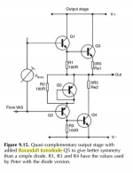
As I've seen recommended by Douglas Self in his schematic in the book the transdiode is made from a pnp transistor, like the driver.
Another interesting thing I saw in LTSpice is that the transistor model (part no) doesn't really matter for overall thd/harmonics distribution.
As I said, 2nd harmonics rise and 3rd harmonics fall as I increase the value of that resistor from 40R to 150R. Even with a bit higher THD I presume even order harmonics are to be desired to odd ones.
As I've seen recommended by Douglas Self in his schematic in the book the transdiode is made from a pnp transistor, like the driver.
Another interesting thing I saw in LTSpice is that the transistor model (part no) doesn't really matter for overall thd/harmonics distribution.
If H2>H3>H4>H5 in a monotonic fall, a la Jean Hiraga from the seventies, then the sound will be pretty good. Yes, evens are always better than odds, particularly from H4 and beyond. H3 is actually musical, if sharp. H5 higher odd orders confer a 'machine' sound, best to be avoided if possible.
The distortion profile is a function of output device, bias, drivers and operation parameters, and particularly the input and VAS stages. I agree, the transdiode doesn't seem to have much influence, and I use a 4001.
Ciao,
Hugh
The distortion profile is a function of output device, bias, drivers and operation parameters, and particularly the input and VAS stages. I agree, the transdiode doesn't seem to have much influence, and I use a 4001.
Ciao,
Hugh
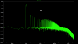
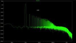
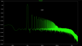
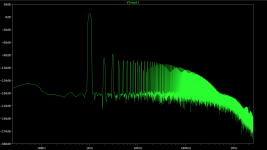
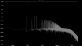
Here are some screenshots of Flat Top window function FFT with different pnp driver emitter resistors at 1W output into 6ohm load at 15.5mA bias, with THD:
40R - 0.001819%
80R - 0.003466%
120R - 0.006514%
150R - 0.008897%
All transistor models I used in this output stage are Keantoken/Cordell models.
40R - 0.001819%
80R - 0.003466%
120R - 0.006514%
150R - 0.008897%
All transistor models I used in this output stage are Keantoken/Cordell models.
Attachments

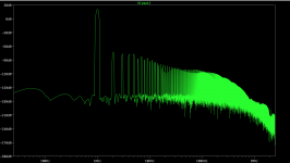
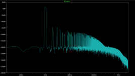
And here's the same settings with 80R and 18W output.
THD holds nice at: 0.003502%
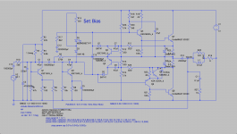
Also attached the circuit schematic.
Q9 is wired wrong way around.
The transistor is currently reverse biased.
But, I could be wrong.
Should there be added resistance in series with the transdiode?
Same value as the Re (=0r5) of the output device?
Same value as the Re (=0r5) of the output device?
Yes, I messed up the connection of the transdiode 
Sadly when I connected it right the result is not that good as before. I get at most the same amplitude of 2nd and 3rd harmonics at about 70R. Lower or higher the 2nd lower and 3rd rise pretty much.
I used a PNP as I've seen in the book of Douglas Self. I attached a screenshot of the schematic he presented. I don't see a 0.5R resistor added in series, but maybe a more detailed implementation could include it. I'm not that knowledgeable as to assert anything.
Attachments
- Status
- Not open for further replies.
- Home
- Amplifiers
- Solid State
- Baxandall diode in quasi complementary design