Hi.
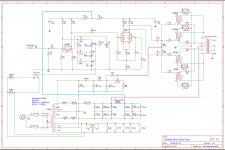
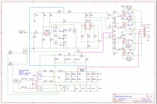
I'm about to build this DIY bass guitar valve amp designed by dhuebert at diytube.com • View topic - Latest Bass Amp and as I've limited experience I'd like to know whether the schematic I've re-drawn using easyeda's browser based software looks correct and to see if any improvements can be made whilst keeping it relatively simple.
It uses a phase invertor from Aiken Amps
under:
Designing Long-Tail Pairs - The Load Line Approach
it used a 6SL7.
I'd like to have a mute switch with light instead of a standby which apparently didn't really serve a purpose other than to allow early manufacturers to use under voltage capacitors! The Valve Wizard
I guess I just need a switch to short the signal to ground but where will make the amp totally silent?
I'd like to make it so maintenance is simple with regards to biasing and valve life. Will something like this work.
Attachments

I just need a switch to short the signal to ground but where will make the amp totally silent?
Will something like this work.
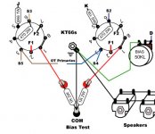
Looks reasonably ok. Why use a dropping capacitor instead of the 50V bias tap on the
power transformer secondary? Even with no overall nfb, I'd still ground the common tap
of the output transformer secondary for safety. You can short the amplifier input to ground
after the 100k, for muting. You could also short to ground just after the tone stack.
Maybe neither one will make the amp totally silent, you'll have to disconnect the speaker for that.
Last edited:
IMO, that is a rather daunting project under the circumstances. Filled with expensive parts and scary-high HT voltages, things could get very ugly if anything goes wrong with the build. This really is the sort of project that should only be built by someone with proper training in high-voltage safety, and with the proper protective gear to avoid electrocution if a mistake is made. 😱Hi.
I'm about to build this DIY bass guitar valve amp
<snip>
I've limited experience
That said, I have one suggestion. As you know, potentiometers use a lightly spring-loaded contact on the rotating wiper arm. This contact is made by pressing against an internal carbon or plastic resistive track. With age, the contact invariably becomes intermittent, and one day, the contact may not exist at all.
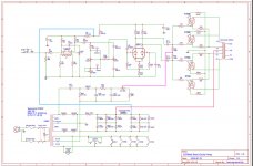
In your circuit, what happens if the output stage bias pot wiper goes open circuit (as one day it will?) Those four large and expensive KT88s are left with their control grids floating at an undefined voltage. Depending on how quickly the problem is noticed, those valves may overheat and cook to death, and may also cause related failures in other even more expensive parts (like the output transformer.)
Fortunately, there is a simple fix. Just connect a 10k resistor from the bias pot wiper to the negative end of C23 (same point as the right end of R36 in your schematic.) The resistor will do almost nothing as long as the bias pot works properly; but if (when) the bias pot fails and the wiper loses contact with the resistive track, the added 10k resistor will pull the KT88 grids to maximum negative bias, shutting them off.
This will stop your amp from working, but it will do so without destroying any parts in the process. Much better than a few cooked KT88s and a cooked output transformer!
For a mute switch, you could connect it between ground and the right end of R10 (in the tone control). The phase splitter and output valves will still be amplifying, and may produce a tiny bit of hiss, but this should be much quieter than Rayma's first suggestion, as it removes the noise from the 12AU7 preamp stages. (Most of the noise in a properly designed and built amp comes from the input stage.)
I see Rayma also mentioned shorting out the signal after the tone stack, and that is what my suggestion implements (switch from right end of R10 to ground.)
Good luck with the project, and please be very, very careful with those high voltages!
-Gnobuddy
Last edited:
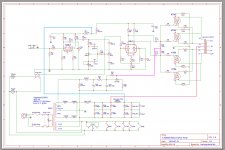
Thanks for the advice rayma and Gnobuddy. I thought the 378cx was the 240v version of the 278cx which dhuebert used but it has the 50v bias tap. Do I just remove the cap as in this schematic? I have built a guitar amp and a reverb unit before and are aware of the safety procedures. It does work out expensive but I just like to play through stuff I've made. At this stage I'm paint by numbers though, as you can probably tell.
Attachments
Last edited:
In addition to Gnobuddy's elaborations on your bias circuitry, I'd provide an individual bias potentiometer for each KT88. This releases you from buying selected quads every time when one tube gets weak.
In my own and very personal opinion this cowtail tone stack is sub par in an instrument's amplifier. Better provide a stack according to Leo Fender's ideas which gives you approved sounds in any control settings (besides all controls set to zero, of course).
Best regards!
In my own and very personal opinion this cowtail tone stack is sub par in an instrument's amplifier. Better provide a stack according to Leo Fender's ideas which gives you approved sounds in any control settings (besides all controls set to zero, of course).
Best regards!
Hi Kay,
Would they replace the 1k5 resistors? I guess they would need a by-pass resistor in case of failure as well. Do you know of a schematic which shows how to do this? I've searched but cant find.
Would they replace the 1k5 resistors? I guess they would need a by-pass resistor in case of failure as well. Do you know of a schematic which shows how to do this? I've searched but cant find.
No, they would't. These 1k5's grid stoppers are essential in high gm tubes to avoid oscillations in the VHF range.
In the meantime I've had a closer look at your schematics. My additional thoughts:
- Replace R2 by a 1M resistor. 10M is waaay too much.
- Decrease R1 to not more than 10k. This in combination with the first triode's input capacitance is sufficient as a RFI filter.
- In difference to Gnobuddy's recommendation I'd chose 100k for R20 (or four R20's 😀).
- Replace R17 by 100k. The difference between R16's 82k and 120k appears a bit too big.
Best regards!
In my own and very personal opinion this cowtail tone stack is sub par in an instrument's amplifier.
I suspect the german term "Kuhschwanz Klangregelung" is not known in anglo-american language. Maybe "Baxandall Equ" comes close, but I am not sure.
Yes, maybe. In German a Baxandall tone stack is an active one, though, but basically with the same eq characteristics.
Best regards!
Best regards!
I just noticed there are two resistors labelled R2 in the schematic. Kay was talking about the one right at the input (and I agree with his recommendation to reduce it to 1 Meg.) But there is a second R2 in the B+ supply to the 12AU7. Weird, I would not have thought Kicad would let this mistake be made.- Replace R2 by a 1M resistor. 10M is waaay too much.
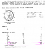
And I will stick with my 10 (or up to 22k) recommendation. 🙂 The New Sensor KT88 datasheet (attached) recommends no more than 100k grid resistance for fixed-bias operation for a single KT88. With two devices biased through the same resistor, R22 and R23 should not exceed 50k; using 100k there is already abusing the datasheet by a factor of 2 (which is commonly done in guitar amps, but that doesn't make it a great idea, and can potentially lead to a runaway condition in the output valves which can destroy them.)- In difference to Gnobuddy's recommendation I'd chose 100k for R20 (or four R20's 😀).
At any rate, with the amount of grid-to-ground resistance already beyond the data-sheet maximum, it is a bad idea to add still another 100k in R20. Which is why I would suggest using 10k - 22k there, no more.
There are no bad side-effects from using 10k as R20, it only has a very slight effect on the linearity of the bias pot. Nothing that would even be noticed in use.
-Gnobuddy
Attachments
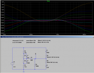
A couple of years ago, I simulated the passive Baxandall circuit in LTSpice to see how it behaved.In my own and very personal opinion this cowtail tone stack is sub par in an instrument's amplifier.
I really did not like the results (see attached screenshot.) Cut and boost curves are very different from each other. For example, at full treble boost, boost starts at 200 Hz, while at full treble cut, the response only starts to fall above 2 kHz!
There are plenty of other problems as well. For example, look at the full bass boost curve - widely spaced from all other curves. This says the bass control is not very linear in use.
Incidentally, the simulation was done with log pots for both treble and bass. (Linear pots gave even worse results.) The equations you see describe the logarithmic potentiometer behaviour, and I derived those equations myself, because at the time I couldn't find a trustworthy model of an LTSpice log pot online.
I am not a fan of the Fender tone stack either, but it is certainly true that it is very widely used, and lots of great guitar tone has been created using amplifiers that incorporate it.
-Gnobuddy
Attachments
I suspect the german term "Kuhschwanz Klangregelung" is not known in anglo-american language. Maybe "Baxandall Equ" comes close, but I am not sure.
Cow-tail is, I assume, the same language play as "swinging inputs", a topology often used on multi-band tone controls.
Bax's paper says "Negative Feedback" in the title:
http://www.learnabout-electronics.org/Downloads/NegativeFeedbackTone.pdf
http://www.thermionic.info/baxandall/Baxandall_NegativeFeedbackTone.pdf
The passive boost-cut was around a long time (at least 1939), and was summarized by James (1949), and referenced by Baxandall.
http://www.thermionic.info/james/James_SimpleToneControl.pdf
Sorry for the multiple device designations. EasyEDA doesn't reasign when you copy and paste like some other programs do. The reason R2 was 10M was to allow up-right bass to go lower apparently but that wont be a problem for me so I'll change it. I'll keep bypass resistor at 10k.
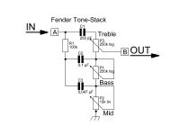
I don't suppose someone could draw a little sketch of the fender tone stack from V1 pin 6 to V2 pin1 those fender schematics are really hard to see/read. If I search fender super bass schematic lots of Marshall schematics show up. I'm not sure which one would fit this amp.
I don't suppose someone could draw a little sketch of the fender tone stack from V1 pin 6 to V2 pin1 those fender schematics are really hard to see/read. If I search fender super bass schematic lots of Marshall schematics show up. I'm not sure which one would fit this amp.
....draw a little sketch of the fender tone stack...
Google _is_ your friend. Many-many re-draws.

....If I search fender super bass schematic lots of Marshall schematics show up.....
Marshall "studied" the Fender stack near verbatim. Over many models at both brands there are differences, but more alike than similar.
TSC is a fun tool:
TSC
Re-make for non-Windows computers:
TSC in the web
Attachments
Yes, Fender's and Marshall's stacks basically are the same - besides the components' values that Jim Marshall had altered, presumably for license reasons. The biggest difference is in the drive, though: Marshall uses a cathode follwer prior to his stack.
Best regards!
Best regards!
You don't need this C1 after the tone stack, as it's capacitors C4, C5, and C6 necessarily have to cope with the plate supply voltage.
Best regards!
Best regards!
- Status
- Not open for further replies.
- Home
- Live Sound
- Instruments and Amps
- Bass Guitar amp advice