I didn't want to pollute the spice model thread with this.
While I wait for parts I have been playing with Spice models. Specifically variations on Millett's PP circuit using the Harmonic Equalizer connection. The circuit runs fine when I attempt to use reasonable resistances but I noticed that no matter what values I used I couldn't force clipping. The output was always a perfect sine wave.
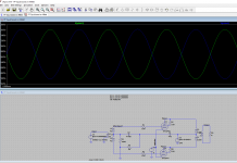
So I turned the bias into a voltage source (breaking the Equalizer connection at the same time) and started really stress testing it. While the Vpp output changed with bias it was always a perfect sine wave no matter how hot or cold I set the operating point. Similarly the two plate voltages were always perfect sine curves 180 degrees out of phase. This does not seem right.
I've attached screen shots for the two plate voltages plus the output taken at zero bias. Not that the peak to peak values change but the behavior is the same with different tube models or if I switch to using a triode symbol and triode models. I'm also getting more change in voltage than I would expect from the turn ratio I used on the output transformer but I'm more worried about the inability to generate distortion.
While I wait for parts I have been playing with Spice models. Specifically variations on Millett's PP circuit using the Harmonic Equalizer connection. The circuit runs fine when I attempt to use reasonable resistances but I noticed that no matter what values I used I couldn't force clipping. The output was always a perfect sine wave.
So I turned the bias into a voltage source (breaking the Equalizer connection at the same time) and started really stress testing it. While the Vpp output changed with bias it was always a perfect sine wave no matter how hot or cold I set the operating point. Similarly the two plate voltages were always perfect sine curves 180 degrees out of phase. This does not seem right.
I've attached screen shots for the two plate voltages plus the output taken at zero bias. Not that the peak to peak values change but the behavior is the same with different tube models or if I switch to using a triode symbol and triode models. I'm also getting more change in voltage than I would expect from the turn ratio I used on the output transformer but I'm more worried about the inability to generate distortion.
Attachments

1) There is no gnd reference on the output part of the speaker transformer. Ground the lower end. Otherwise output curves are meaningless.
2) Is the 6f12p tube the pentode half of a russian 6Ф12П ?
If so, you run it at 10W which is 2x max dissipation which is 5W. To get down to 5W increase bias to 2.5V.
3) OPT inductances of 1500H are unrealistic - at least for the 5kHz signal. More like 1.5H primary and 3mH secondary. Also 2ohm primary DCR is unrealistic, more like 200 ohm.
4) Why does your .tran statement have a stop time of 100 seconds and a min. time step of 0.01s = 10ms ? For your 5kHz signal 1ms stop is appropriate. And delete the min step parameter all together and let spice decide by itself, or use 1 us if you must.
5) With these changes output clips at 8V (4V input).
6) To examine distortion spectrum, right klick on the black signal display area - view - FFT - and select the signal you want to analyse. You will get a distortion spectrum plot as a result.
7) For a readout of a THD figure, add a ".four 5k v(output)" directive - 5k is your choice of signal frequency, v(..) can be any circuit node e.g. output. Now run the sim again and right click the display area and select - view - spice error log - to get THD figures % displayed.
Thank you for all of the responses but especially for #1 (that was simply a stupid mistake but probably the initial point of failure!), #6 and #7. I already knew my output transformer was massively messed up which is why I was mostly looking at the plate outputs expecting to see clipping there with a zero bias and 2.8 to 4Vpp voltage on g1.
You are correct on the tube although I have plugged in more or less all of the pentode models I have. Similarly I have tried many different bias voltages from 0 to very high trying to see either clipping or cutoff. Thus the specific values shown are known to not be reasonable operating points simply the end points of a series of increasing frustration.
You are correct on the tube although I have plugged in more or less all of the pentode models I have. Similarly I have tried many different bias voltages from 0 to very high trying to see either clipping or cutoff. Thus the specific values shown are known to not be reasonable operating points simply the end points of a series of increasing frustration.
Furthermore, your setup is completely symmetrical. A mathematical algorithm like spice's will therefore cause *total* elimination of *all* even harmonics, except for rounding errors in the tenth decimal ... most circuits have a single ended input tube whose distortion pattern cannot be cancelled, but yours is p-p and nothing but p-p, so everything cancels out.
In reality both tubes will not be identical, and may differ by 10, 20 or more %.
Both sides of the transformers will not be identical but have slightly different inductance and DCR, both input and output transformers.
And the simple transformer model is mathematically ideal, no saturation effects or other non-linearities whatsoever present.
By the way, your input T will not have 2ohm DCR but more like in the hundreds of ohms.
Just as an exercise, make your transformers a little bit unbalanced, and since you have different models for the tube available, use one model for the upper tube and a different model for the lower tube and see how harmonic distortion shows up in the FFT graph ...
Thanks.
That's certainly all true but your original response had the key result. Grounding the output and changing the resistance in the output transformer cleared things up. I'm still a little surprised that at zero bias I don't see visible clipping/distortion but that is probably simply an incorrect expectation on my part.
I wanted to simulate the circuit to at least roughly check some load line calculations. Certainly real tubes won't be as perfectly symmetrical and real transformers won't be as idea. But it's a good way to do a little useful dabbling while waiting for tubes to arrive.
... at zero bias I don't see visible clipping/distortion ...
This would not surprise me if the spice model for the tubes did not model grid current ...