Im looking at the WE300B chart, published 1950.
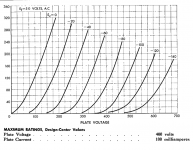
It says maximum ratings, Design -Center values.
Does design-center mean "Dont design for more than __" ??
It lists Plate voltage at 400, Plate current 100mA..
My main question, on the characteristic chart, the plate voltage goes way up to 700v and the plate current all the way to 320mA..
Why do they bother showing any data well above the recommended ranges ??
90% of the chart is above maximum's. I feel like im missing something basic...
Attachments
Design center is just that, people design for operation on both sides of that value. (Or more/less conservatively)
A tube operating at 400V and 100mA might see peak plate voltages of over 700V.
These curves are used to derive the optimum load impedance for the stated operating conditions hence they extend beyond the design center.
My amps were designed about 400V/80mA I ended up with a 5K primary... hmmm.. 🙂 See if you can figure out the load line.. 🙂
If you make a million radios, and do not test every one, aim for "Design Center". This gives a lot of leeway for wall-voltage, your parts tolerances, and the tubes' tolerances.
If you are going to measure every radio (TV) you make, you may use Design Max. (300b may not have such a rating, it is reckless.)
In operation at say 300V 80mA, the tube plate "might" swing to 600V open-circuit, or 160mA short-circuit, or some in-between values for happy loads. The curves really should support interpolation of audio peaks to twice expected _DC_ bias. (A triode will not swing twice, but will swing a lot.)
And I would add that despite it says max plate voltage 400V and max plate current 100 mA I would never run a standard 300B so hard.
400V is ok. Good quality 300B can take 450V too. 100 mA is hard on any standard 300B even at anode voltage lower than 400V.
Last time, with a good quality Chinese 300B I found a sweet spot at around 420V/70mA with 4.5K load. This already gives 9W+ in class A1. I was able to get about 12W at 5% THD with moderate positive grid drive using my usual DC coupled cathode follower.
So no need to run it harder...
If want more power the PSE is a good idea. Very likely by the time the 2 300B's in the PSE get weak, in the SE that runs the 300B at 100 mA you will have put more than 2 per channel for sure....so the PSE is cheaper on the long run and get more power at lower distortion.
Interesting comment on A2 power output and PSE, my next 300B amplifier is likely to have both and ~2 - 2.5K primary impedance.
I have had some Chinese made Valve Arts tubes self destruct in the past at 400V on the plate. The grid did not fully shroud the filament and above 350V the grid would loose control of the plate current. (The plate extended slightly above the grid structure.)
I have used JJ 300B for the most part without too many issues for the past 20 years.
Design Center is for Quiescent voltages, currents, etc.
Tube curves have to include much more than the Quiescent conditions, or you would have to design at values such as 200V instead of 400V, 50mA instead of 100mA, etc.
That is because you have to allow for signal swings which bring the tube outside of quiescent conditions.
When a single ended amplifier plate is at 400V quiescent; and then the maximum signal takes the plate current to near cutoff, then the plate will be near to 800V.
I hope that clarifies the concept.
Last edited:
When Audio Note was run by Kondo San most of his amps were PSE. So I spent a bit of time on this and in the end could see the reasons.Interesting comment on A2 power output and PSE, my next 300B amplifier is likely to have both and ~2 - 2.5K primary impedance.
Especially the 2A3 PSE in comparison to 300B SE: similar power and THD figures, but the 2A3PSE runs at 250-270V with 1.25K-1.5K OPT.
In turn, in the 15-25W power range the 300B PSE becomes more convenient than high voltage tubes.
I have used mostly Golden Dragon in the past. Especially at the beginning, when they were doing a titanium plate version called 4-300B-LX (very nice tube), they were pretty good.I
I have had some Chinese made Valve Arts tubes self destruct in the past at 400V on the plate. The grid did not fully shroud the filament and above 350V the grid would loose control of the plate current. (The plate extended slightly above the grid structure.)
I have used JJ 300B for the most part without too many issues for the past 20 years.
Today I would buy the Billington Gold Special Edition which is best of what they stock.
JJ's are good too.
I used to occasionally service AN Japan (later Kondo) and a limited amount of AN UK gear as well. Mostly Ongaku, a few Keegons, and a nice clone of the Ongaku made by Audio Marginale in Quebec province. Nicely built stuff. I liked Kondo, a very honorable man. Never met in person, did talk on the phone a few times via his business partner who spoke good English. The insurance cost of having that stuff in my lab was astronomical. Most beautiful build quality of anything I have ever seen. My own stuff isn't nearly as pretty (or common).
In fact for some perverse reason I am thinking of building a pair of PSE 300B amplifiers as replacements for the current GM70 based LF amps in my system - I only need 15 - 20W or so, and the substantially lower power consumption and reduced heat for about the same power is appealing. I had planned on something more exotic, but the dawning realization that retirement is not many years off and replacement costs of anything more ambitious than 300B and GM70 may put them out of reach. OTOH the GM70 do a great job and are cheap and reliable. (Amps just overhauled and updated should be good for another 5 - 10 years)
In fact for some perverse reason I am thinking of building a pair of PSE 300B amplifiers as replacements for the current GM70 based LF amps in my system - I only need 15 - 20W or so, and the substantially lower power consumption and reduced heat for about the same power is appealing. I had planned on something more exotic, but the dawning realization that retirement is not many years off and replacement costs of anything more ambitious than 300B and GM70 may put them out of reach. OTOH the GM70 do a great job and are cheap and reliable. (Amps just overhauled and updated should be good for another 5 - 10 years)
I'm thinking that paralleled (identical) valves with their filaments connected in opposite polarity will sum to null the residual second order modulation from AC heating. Hope to test this before the year is out, but if you start with AC heating you might beat me to it. If so, hopefully you'll report results. You've always been great about spreading the Good Word.
All good fortune,
Chris
All good fortune,
Chris
Parallel Single Ended. Normally 2x 300Bs (or other output tubes) in parallel per channel to get double power.
45, ty!
May be a piece of the puzzle was found early this am. Didn't realize that the vertical column was based on plate current determined by assuming the tube had a dead short. So, now i add DCR of opt to cathode resistor value and then E/R will give me the maximum mA to use... now my load line makes sense! And, now the grid bias fits in nicely... Time to reread everything, as this stumbling block prevented me from soaking in everything else...
May be a piece of the puzzle was found early this am. Didn't realize that the vertical column was based on plate current determined by assuming the tube had a dead short. So, now i add DCR of opt to cathode resistor value and then E/R will give me the maximum mA to use... now my load line makes sense! And, now the grid bias fits in nicely... Time to reread everything, as this stumbling block prevented me from soaking in everything else...
I'm thinking that paralleled (identical) valves with their filaments connected in opposite polarity will sum to null the residual second order modulation from AC heating. Hope to test this before the year is out, but if you start with AC heating you might beat me to it. If so, hopefully you'll report results. You've always been great about spreading the Good Word.
All good fortune,
Chris
Tiis is normally I do but p-p of 300B; the PSE for 300B, in my opinion, is a not convenient job.
A right p-p biased for the 50% in class A ( never go in A1, A2, A3,A4!) with proper trafo will have better performances and more efficency
Walter
Tube characteristic chart question
Take 2 on my basics question...
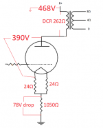
I'm trying to understand whats going on, in a way where once I do, it will be mine forever... that said, the attached shows a scaled down version of my 300B schematic.
If the 300B was a dead short, the total DC resistance would be
262Ω + 12Ω + 1050Ω = 1324Ω.
468v/1324Ω = .353A or 353mA
(Orange Line in 2nd image)
Across the cathode resistor I measured a 78 volt drop. (74mA)
(Green horizontal)
Question 1. To determine Ec Do I add the combined voltage drop across both of the 24Ω resistors 74mA*12 = 0.89
(0.89V + 78) or about 79V
Is 79V the screen grid negative bias and Ec ?
The Cathode resistor measured 1050Ω so there is 74mA. The load line and curves don't line up well. I know Im probably splitting hairs, but I also dont have a feel for how off is too off, and the negatives for deviations (small to big)
#2) Did I at least get the fundamentals, or am I missing something ?
Its also making me nuts than many mention trying to keep the bias current at about 70mA, but I guess I should save that for another post.
Take 2 on my basics question...
I'm trying to understand whats going on, in a way where once I do, it will be mine forever... that said, the attached shows a scaled down version of my 300B schematic.
If the 300B was a dead short, the total DC resistance would be
262Ω + 12Ω + 1050Ω = 1324Ω.
468v/1324Ω = .353A or 353mA
(Orange Line in 2nd image)
Across the cathode resistor I measured a 78 volt drop. (74mA)
(Green horizontal)
Question 1. To determine Ec Do I add the combined voltage drop across both of the 24Ω resistors 74mA*12 = 0.89
(0.89V + 78) or about 79V
Is 79V the screen grid negative bias and Ec ?
The Cathode resistor measured 1050Ω so there is 74mA. The load line and curves don't line up well. I know Im probably splitting hairs, but I also dont have a feel for how off is too off, and the negatives for deviations (small to big)
#2) Did I at least get the fundamentals, or am I missing something ?
Its also making me nuts than many mention trying to keep the bias current at about 70mA, but I guess I should save that for another post.
Attachments

....The load line and curves don't line up well.....
No.
The loadline must pass through the DC operating point 390V 78mA.
The loadline should be as symmetrical as possible; yours is grossly lopsided.
An ideal device would swing from 78mA, to zero mA, to 156mA, and back.
A tube's curvature makes the low-current zone undesirable. As a rough hack, plot from DC OP, to half that, to 1.5 times that, and return. Swing from 39mA to 117mA. The 117mA happens about at the zero-grid line. The 39mA will be the same distance (on the Vp scale) the other way.
I am seeing 300V peak and 39mA peak. The load impedance must be 300V/39mA or 7.7K. The RMS output is 212V and 27.5mA or 5.8 Watts RMS. Tube dissipation is 30.4W (so, 19% efficiency). Total DC power input (including bias and losses) is 36.3W.
Attachments
You're operating into a transformer, so you'll want to consider the output valve's idling condition from two different points of view. From the DC point of view, your calculations are correct. This will always be important, but it doesn't determine the valve's actual operating condition when driven by signal.
The valve's actual loadline in the audio frequency range is determined by the audio frequency load, which is in turn determined by the output transformer's ratio and the actual load on its secondary windings. The "reflected" load that the valve sees is the winding ratio squared times the secondary load. For example, an output transformer with a turns ratio of 20:1 feeding a load of 8 Ohms presents a load to the valve of 20 x 20 x 8, or 3200 Ohms. All stuff that you already know.
The cool part of these characteristic curves is that that number (3200 Ohms) is also the slope of the loadline, and can be drawn onto the curves. In your example, you would make a point at your proposed idling point, 390 Volts and 74mA.
Then you'd make another point on the Y axis (current) pretending that things were a simple 3200 Ohm resistor. So: 390 Volts / 3200 Ohms = 122mA. This is added to your starting point of 74mA, to make 196mA, and another point is made, on the Y axis at 196mA. Why? Because this is the current that a 3200 Ohm resistor would draw, if a woodchuck could chuck wood.
Now we draw a line that includes these two points. This *slope* is 3200 Ohms. It's the slope that matters, and if you have an adjustable triangle, you can slide this slope around all over your graph of plate curves and it will still apply. And we see that our first guess is far from ideal. Why? As PRR has said, the first-guess operating point (idling point) is way too far to the right. Music signals must swing equal distances in both directions along the loadline. The low current "knee" characteristics of all valves (and all other practical amplifiers) also encourages us to bias things up and left, for linearity, and in this case, max output.
And if you're not designing for best linearity, why would anyone bother with all of the sturm und drama of a 300B amplifier?
All good fortune,
Chris
Last edited:
(0.89V + 78) or about 79V
Is 79V the screen grid negative bias and Ec ?
I'd missed this point, but yes you've got it!
To sit at the cool kids table, you'll want to call this "control grid" or G1 and "Eg" but you've got the right handle on it. It's tough to try to figure this stuff out over the internet. Fortunately, the basics are completely understandable, with no quantum voodoo needed. Everything about valve operation at audio frequencies that I've ever heard of is completely common sense, unlike anything else in modern life.
All good fortune,
Chris
No.
The loadline must pass through the DC operating point 390V 78mA.
Again, im still in my infancy and trying to learn. Not to contradict but one book i have and the link below,
Drawing Load Lines and this video at about 10:10 Tube Theory part 3 - YouTube
Is saying that the horizontal voltages on the characteristics sheet is more or less if the tube was a dead short. That the right slope should be at B+
Am I not understanding correctly?
I know this amp is out of line, but before I can dial it in I need a perfectly clear understanding of the basics..
Last edited:
Those references are for an actual resistor, in series with the valve, as the loadline. The signal sees the same loadline as a selection of batteries biasing the grid would give. With a transformer load, the AC (signal) loadline can be, and is, different from the DC loadline. Does that make sense?
All good fortune,
Chris
All good fortune,
Chris
So today is the day where 99% of what im doing has been filled with mistakes
.. hoping the following is the exception!!!
Im under the impression that the load line is determined by a DC analysis only. B+ is DC, the OPT can be considered a plate resistor by measuring its DCR. That the plate of the tube has its own varying resistance, at different voltages changes. That said, the total dc path and sum of R values (except the tube itself) are taken into consideration while determining the load line. If the tube was off, not allowing any ac through the grid, that the tube would actually be at B+ on the plate. Again only what im understanding is the OPT can store energy and cause higher than B+ at the plate. Again, except for this thread, everything I have learned says that B+, circuit resistance is used to get the left vertical mA value. From that line, you see what the negative grid bias is and make your first "dot"
As far as an actual resistor, the OPT is one, and cathode resistance is the other. So, Im trying to reconcile what is written above vs everything else I have to follow you guys..
Ultimately my amp is "tweaked" not in bad way, but i hope to dial it in. Maybe someone can explain what im missing
- Home
- Amplifiers
- Tubes / Valves
- Basic 300B Tube characteristic chart question