Hi all-
I was just asked about building a passive balanced cross over. Now I have NEVER seen one, but I'm sure it has been built.
Searches here yielded nothing so I was hoping someone might have a reference or experience they can share.
The requirement is 6- 12 db / oct high pass <passive and balanced>.
The initial ASSUMPTION is to mirror the circuit to the 2 signals to the common conductor and calculate the values as a single ended passive XO and apply to both sides.
Sound about WRONG enough? 😀
Again any starting point would be appreciated.
Hi,
with passive cossover You mean the typical cr placed between poweramp and driver, or a highlevel cr placed between pre- and poweramp?
In the first case the transformation is easy. Split all series elements in two equal ones. Half the value of Inductances and resistors and doublet he value of caps. Place one of the two in the positive, i.e noninverting branch and the other in the inverting path (i.e. gnd). parallel elements remain the same.
jauu
Calvin
Hey Calvin-
Thanks for the reply. You guessed it.. An odd situation where someone wants to try a passive balanced crossover on the "hi-z" or signal side <before the amps>.
Excellent. I would have calculated each side as it's own value and would have been way off.
Now I have never made a passive signal xo.. Other than the Harris mods for automotive use I don't know of any in existence. Does anyone has a schematic with values and frequency I can use as a starting point?
Hi,
symmetrical filters implemented with active OP-amp circuitry is desxcribed here:
TI/BB, SLOA064 "A differential OP-amp circuit collection" july 2001
TI/BB, SLYT343 "Using the infinite-gain, MFB filter topology in fully differential active filters" from Analog Applications Journal 3Q2009 www.ti.com/aaj
could give You a hint on how to design passive circuitry too.
jauu
Calvin
Again, thank you Calvin. I will read those now.
As you see it is an "odd" device and not much material on it.
As you see it is an "odd" device and not much material on it.
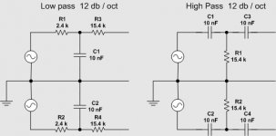
According to this:
http://focus.ti.com/lit/an/slyt343/slyt343.pdf
the following should be good for 10K slopes.
I would assume changing the resistors is easier than changing the caps due to available values..
http://focus.ti.com/lit/an/slyt343/slyt343.pdf
the following should be good for 10K slopes.
I would assume changing the resistors is easier than changing the caps due to available values..
Attachments
- Status
- Not open for further replies.
- Home
- Source & Line
- Analog Line Level
- Balanced "passive" crossover