All thoughts and comments welcome. Please help me point out problems, errors and suggestions for improvements.
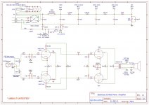
The goal is balanced input, negative feedback and around 25-35 watts.
Per Eli Duttman’s suggestion in post #3 in this thread
https://www.diyaudio.com/forums/tubes-valves/349589-7591a-amp-design-35w-x2.html
I am incorporating combination bias for the 7591’s They will be new production.
New production 5AR4’s seem to arc over easily so i’ve added some diodes to help that problem.
Not sure I have the negative feedback exactly correct but hopefully it’s close. Everything else is pretty straight forward.
I plan on building 2 to make a stereo pair, Attenuator is stepped so stereo balance can be maintained across the pair.
Attachments
Could use a single balanced T attenuator, instead of two unbalanced ones.
Fewer parts and decks, and would work better, especially since the
attenuators are part of the nfb networks.
Fixed Pi & T Attenuators - Equations - RF Cafe
Fewer parts and decks, and would work better, especially since the
attenuators are part of the nfb networks.
Fixed Pi & T Attenuators - Equations - RF Cafe
Last edited:
I have two thoughts on the wiring of your OPT. The speaker is connected between the 4 ohm tap and the 8 ohm tap. This is not 4 ohms worth of winding it's more like 2 or 3. If your speaker is 4 ohms it can be connected between the 0 and 4 taps, or the 4 and 16 taps. If your speaker is 8 ohms it needs to go between 0 and 8. The only perfectly symmetrical connection is a 16 ohm load on the 0 and 16 ohm taps.
I experimented a bit with a completely balanced circuit similar to yours. I found that most attempts to run balanced feedback from the OPT secondary fails at the frequency extremes unless a very good OPT is used. Due to unequal parasitics in the OPT you may get unequal phase shifts in your feedback paths at both ends of the audio range leading to increased distortion and possible instability.
Somewhere during those experiments Pete Millett created his Engineers Amp and I played with it a lot. It uses a new take on an old concept to use balanced feedback from the PRIMARY of the OPT and single ended feedback from the secondary to the input stage as seen in a typical amp. I liked my builds of his amp with a bit more of the balanced feedback, and zero single ended GNFB.
Posted new P-P power amp design
See also the RCA 50 watt circuit in post #1 here. It is the old concept I mentioned. Some of what is discussed in this thread is where we ran off in different directions with the same concept I have a 250 watt UNSET P-P amp running on a breadboard:
If UNSET and the RCA50W Had a Baby
Yes, Audio Research Corp. used this balanced feedback connection for many years, and it worked well
with their custom made output transformers. They also combined it with partial cathode coupling.
with their custom made output transformers. They also combined it with partial cathode coupling.
Since I didn't see an input coupling capacity and with a 4.2V DC note on the input, what DC bias are you planning for the 6AH6? Do you really want to leave your input bias depending on the input XLR source?
The input grids are at ground potential, so no input capacitors are needed.
The input cathodes go to a current source which is connected to a negative supply.
The input cathodes go to a current source which is connected to a negative supply.
Last edited:
I would not trust that the incoming signal is balanced, i would convert to unbalanced and make a classical phase inverter for the power tubes.
I experimented a bit with a completely balanced circuit similar to yours. I found that most attempts to run balanced feedback from the OPT secondary fails at the frequency extremes unless a very good OPT is used. Due to unequal parasitics in the OPT you may get unequal phase shifts in your feedback paths at both ends of the audio range leading to increased distortion and possible instability.
Thanks for that information. I will read those links and rethink that aspect of the design.
Don't understanding the filtering in the heater's rails.
Not meant to be filtering the .33 resistors will only be necessary if the heater rail voltage is above 6.7V It maybe in spec sense it should be pulling 3A total.
Yes, Audio Research Corp. used this balanced feedback connection for many years, and it worked well
with their custom made output transformers. They also combined it with partial cathode coupling.
I didn't know they did that. I'm starting to think custom output transformers are going to be necessary or change it to an unbalanced design.

I would not trust that the incoming signal is balanced, i would convert to unbalanced and make a classical phase inverter for the power tubes.
Input stage is a differential amp - it IS a phase inverter - doesn't need a balanced input.
Schade feedback may work out better - this has feedback varying with volume setting.
I would not trust that the incoming signal is balanced, i would convert to unbalanced and make a classical phase inverter for the power tubes.
The current source under the input pair will tend to balance an unbalanced signal. Not perfectly, but then neither is any practical unbal-bal converter.
You mean a line transformer ??The current source under the input pair will tend to balance an unbalanced signal. Not perfectly, but then neither is any practical unbal-bal converter.
- Home
- Amplifiers
- Tubes / Valves
- Balanced 35 Watt Amplifier Design