A slight disagreement ensued in another thread (Mullard 5-20) regarding balance in long tail pair phase splitters, where the "tail" is a CCS. My contentions were (and are):
1. The CCS does not assure DC balance.
2. The CCS does assure AC balance IF the plate loads are balanced. The phase splitter balance is dependent on plate load matching and nothing else.
3. The AC balance is absolutely independent of the tube matching.
As a rather dramatic demonstration of the power of the CCS tail, I set up the attached circuit. One half of the LTP is an ECC81, the other half is an ECC88. The mu, transconductance, and plate resistance of these tubes are wildly different, so this goes well beyond matching sections.
(more in next post)
Attachments
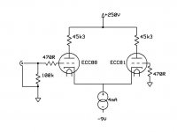
The test circuit was put together in my usual neat and careful fashion- i.e., it was a total mess. The CCS was a bipolar cascode, using the old diyAudio boards- it's similar to the bipolar CCS circuits in "Valve Amplifiers," 3rd edition. There is no provision for balancing or feedback, other than matching of the 45k3 plate resistors.
The supply voltages were as follows: B+ was 250V, B- was -9V.
Now, does the CCS cause DC balance? The voltage at the ECC81 plate was 205V, meaning that about 1mA was flowing through it. Plate voltage of the ECC88 was 118V, meaning that about 2.9mA was flowing through it. Clearly, the DC conditions are NOT balanced. But do they need to be in order to form an ideal phase splitter?
(more in next post)
Attachments

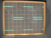
And proof of the pudding: with 0.4V peak to peak square wave input, here's the output (4.8V p-p for both sides). The balance is about as good as can be eyeballed on the scope.
CCSed LTPs do NOT require any sort of tube matching or feedback or any other fancy scheme for AC balance, even with GROSS tube mismatches.
CCSed LTPs do NOT require any sort of tube matching or feedback or any other fancy scheme for AC balance, even with GROSS tube mismatches.
Attachments
Innertesting... now if the tail is a simple resistor, what is the effect of the plates with and without a current mirror load?
WRT DC balance
WRT AC balance
?
_-_-
WRT DC balance
WRT AC balance
?
_-_-
SY - I value your efforts , but that pudding is proofed long time ago ......
I reckon that you know Tek and HP SMs better than me

I reckon that you know Tek and HP SMs better than me
Theory (Kirchoff's current law) holds true. Who'd a thunk. Moral of the story: use a CCS, and stop the fancy balancing schemes. Balance inherent to the topology, not the device.
Nice job, SY.
Nice job, SY.
. Clearly, the DC conditions are NOT balanced. But do they need to be in order to form an ideal phase splitter?
(more in next post)
No, because its two AC signals you want not a DC signal.
However if the DC conditions are way out you might get one phase clipping before the other.
The DC unbalance and AC balance with CCS tail seem pretty much as expected. There likely are some other reasons to keep the tubes more matched though. I would think distortion would increase if the two tubes are not operating from the same point on their characteristics. Not to mention some loss of headroom if the DC balance is off far enough.
Then there are some subtle issues with LTPs that I have never seen addressed anywhere. Fred N. used an interesting setup where the normally undriven side of the LTP was provided a matching inverted signal by a pos. feedback path from an LTP output (a resistive divider from opposite plate to ground to provide a signal for the slack grid matched in amplitude, but inverted, with the input). I have seen something similar in RDH4 I think. The idea would be to symmetrize the operation of the two tubes with AC. Otherwise the input pushes them off center one way always. The question here would be whether an improvement in distortion is gained despite the pos. feedback.
Then there are fixups to LTP distortion like the critical tail resistance to null the 3rd harmonic. A slightly different resistance can be used to null out each of the other odd harmonics. If one were to use a non-linear tail resistance, like some thermionic diode for the tail (of a specific conductance), could one null out ALL the odd harmonics.
And finally, one could really shoot for the moon with an error correction LTP splitter scheme. Here one would simply provide a second resistive divider from non-opposite and opposite outputs back to the driven grid input as well (beside the 1st divider for the slack grid). This divider would be used to subtract a scaled down output from the input signal, so that only -error remained plus the required grid drive to maintain the output status quo. The whole thing looks like a multivibrator then, with loop gain just short of that required for oscillation. The -error residual drives the LTP to eliminate the error exactly (near unity loop gain, the LTP can still have real output gain though). So the LTP always computes the output to satisfy no error with the input. (OK, this scheme will never work for feedback phobic DIYers)
Don
Last edited:
To be clear (for those who weren't following the other thread), these results are exactly what would be predicted by conventional engineering. But there's so much widespread misunderstanding of this circuit that it seemed like it would be nice to dispose of a bunch of them at once, showing the results explicitly and (I hope) dramatically.
Well done SY!
How would smallish Cathode resistors (c-ccs-c) change the outcome, just curious.
EDIT: the discussion started about here I think.. http://www.diyaudio.com/forums/tubes-valves/156699-mullard-5-20-kt88-pp-blocks-15.html#post2065693
Cheers Michael
How would smallish Cathode resistors (c-ccs-c) change the outcome, just curious.
EDIT: the discussion started about here I think.. http://www.diyaudio.com/forums/tubes-valves/156699-mullard-5-20-kt88-pp-blocks-15.html#post2065693
Cheers Michael
Last edited:
Well done SY!
How would smallish Cathode resistors (c-ccs-c) change the outcome, just curious.
Thanks. They'll change the gain (by changing the effective plate resistance) but will have no effect on the balance. Kirchoff forces balance for equal loads.
How would smallish Cathode resistors (c-ccs-c) change the outcome, just curious.
Trimming their values you change voltage drops on them changing bias voltages, such a way you set DC balance in order to get equal voltages on anodes.
Thanks. They'll change the gain (by changing the effective plate resistance) but will have no effect on the balance. Kirchoff forces balance for equal loads.
Oh no, you've let my last secret out of the bag.. 😛 One thing to mention is that adding those little resistors does a couple of things including reducing the gain of the LTP, and also raises the rp further. It should also help somewhat with dc balance (it is local current feedback) which is precisely one of the two reasons why I used to do it - the other being able to tailor the LPT gain to my purposes.. (Note that I often did this with LTPs with long tails to -200V supplies and the like, and only used a CCS occasionally.)
Last edited:
Kevin, you had me confirmed on what I expected on the DC imbalance, would be a bit puzzled if it wouldn't do anything. Say a 100 Ohm cr, if the currents still stands that would set ECC88 Ugc back by 0,19 Volt and that would do some change.
Cheers Michael
Cheers Michael
- Status
- Not open for further replies.
- Home
- Amplifiers
- Tubes / Valves
- Balance in CCS Long Tailed Pairs