Hi all,
one question i always asked to myself, what pros and cons are those waveguides at midrange, bass driver in some designs.

ok, this is a real expensive speaker (something for the eyes ; ) , but i saw this at cheap shoutboxes also.
so, benefits more directivity in front of the speaker ? and still using a rounded baffle ?
only for looking fancy ? makes sense ? better for positioning at wall ?
we all try to flush mount our drivers to avoid diffraction, this is looking to me as it would create diffraction. or do they not ?
help me to understand this 😉
one question i always asked to myself, what pros and cons are those waveguides at midrange, bass driver in some designs.
ok, this is a real expensive speaker (something for the eyes ; ) , but i saw this at cheap shoutboxes also.
so, benefits more directivity in front of the speaker ? and still using a rounded baffle ?
only for looking fancy ? makes sense ? better for positioning at wall ?
we all try to flush mount our drivers to avoid diffraction, this is looking to me as it would create diffraction. or do they not ?
help me to understand this 😉
Not sure I can help with ultra-fi but sharp edges that are very close to a driver and are part of the design to shape the radiation pattern (e.g. the DXT guide on the SEAS tweeter) can change the frequency response without introducing any significant detrimental phase-related effects. Sharp edge = bad doesn't always hold though it usually does.
Well designed 4 way speakers with rounded baffles and cleanly mounted drivers can provide good horizontal directivity comparable to speakers with fewer ways and waveguides. Not sure whether this applies to whatever is in your picture but a Vivid Giya is perhaps an example. The beamwidth tends to be wider than typical "studio monitor"-type speakers and to narrow with rising frequency rather than seeking a constant directivity. Listening tests (e.g. the JBL M2 vs the Revel whatsit) suggest this is a more preferable directivity for listening to music in the home though that perhaps needs a degree of qualification. The better studio monitors have the directivity they do for good reasons.
Well designed 4 way speakers with rounded baffles and cleanly mounted drivers can provide good horizontal directivity comparable to speakers with fewer ways and waveguides. Not sure whether this applies to whatever is in your picture but a Vivid Giya is perhaps an example. The beamwidth tends to be wider than typical "studio monitor"-type speakers and to narrow with rising frequency rather than seeking a constant directivity. Listening tests (e.g. the JBL M2 vs the Revel whatsit) suggest this is a more preferable directivity for listening to music in the home though that perhaps needs a degree of qualification. The better studio monitors have the directivity they do for good reasons.
These days the Magico speakers are designed with the use of a Klippel Nearfield Scanner, so I guess they are aware of what it does in their case.
I can only attest as to why I used round-overs myself, I'm re-using a post I've written a while ago.
The shape of the cabinet determines a lot of what the off-axis energy looks like.
A while ago member @fluid ran sims for a driver in a flat baffle and the same driver with a rounded enclosure, the last example in
this row (with the set back or we could call it a short waveguide) is what I used, based on a hunch, but apparently a good one...
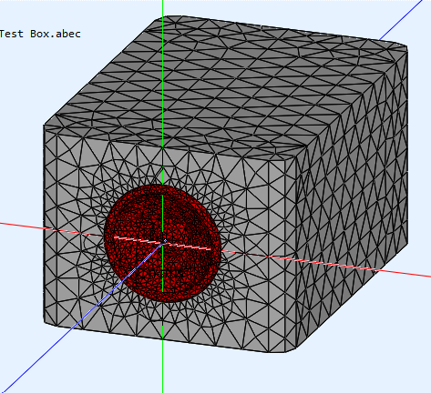
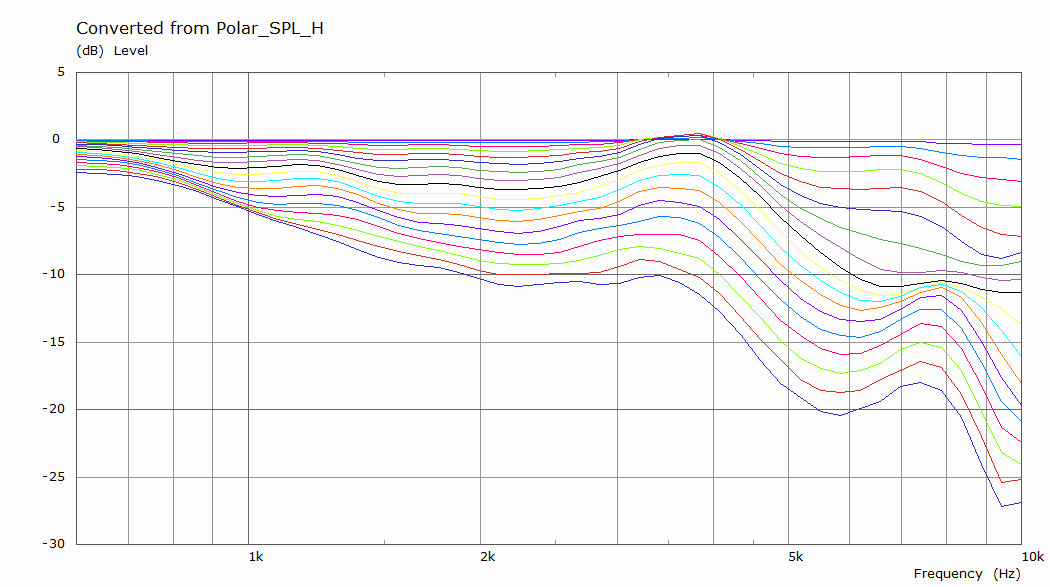
The relatively flat baffle with flush mounted driver simulation in ABEC:
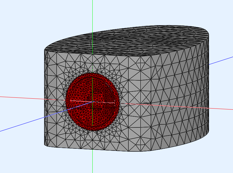
Versus the rounded enclosure with flush mounted driver:
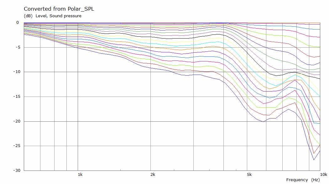
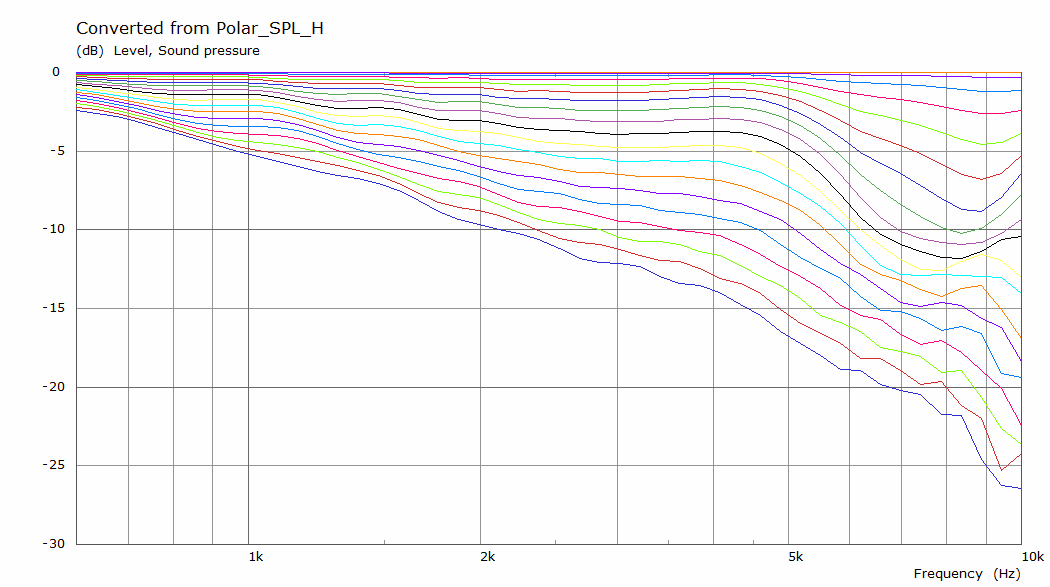
I'd say it is easy to spot differences. The first round-over used on that enclosure shape is only 25.5mm or about 1" radius. Yet the effect it has is quite obvious. A 2" round-over would get you enough of a noticeable effect i.m.h.o.
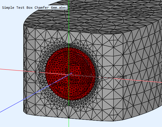
Taking this concept a step further, with the driver set back in the baffle with a small chamfer in front of the driver:
In my case I used a round-over as the waveguide shape.
I'd say it's well worth it to try or play with things like that. It does show much the shape of the enclosure can determine the outcome. Even such a small waveguide like shape in front of the cone does have an influence. The lower we go in frequency, the bigger those round-overs should be to have any effect though. But the enclosure shape and baffle details do matter.
I had chosen my enclosure shape on a hunch, but did play extensively with ripple tank software to verify it I had at least a good hunch. I had already seen measurements of a fullrange driver like the ones I use behind a small waveguide. The ABEC sims that were done years later seem to confirm that my line of thinking was worth the trouble.
I can only attest as to why I used round-overs myself, I'm re-using a post I've written a while ago.
The shape of the cabinet determines a lot of what the off-axis energy looks like.
A while ago member @fluid ran sims for a driver in a flat baffle and the same driver with a rounded enclosure, the last example in
this row (with the set back or we could call it a short waveguide) is what I used, based on a hunch, but apparently a good one...
The relatively flat baffle with flush mounted driver simulation in ABEC:
Versus the rounded enclosure with flush mounted driver:
I'd say it is easy to spot differences. The first round-over used on that enclosure shape is only 25.5mm or about 1" radius. Yet the effect it has is quite obvious. A 2" round-over would get you enough of a noticeable effect i.m.h.o.
Taking this concept a step further, with the driver set back in the baffle with a small chamfer in front of the driver:
In my case I used a round-over as the waveguide shape.
I'd say it's well worth it to try or play with things like that. It does show much the shape of the enclosure can determine the outcome. Even such a small waveguide like shape in front of the cone does have an influence. The lower we go in frequency, the bigger those round-overs should be to have any effect though. But the enclosure shape and baffle details do matter.
I had chosen my enclosure shape on a hunch, but did play extensively with ripple tank software to verify it I had at least a good hunch. I had already seen measurements of a fullrange driver like the ones I use behind a small waveguide. The ABEC sims that were done years later seem to confirm that my line of thinking was worth the trouble.
Last edited:

A sphere does diffract. (A continuing baffle (eg flat) wouldn't.)
You see in that case diffraction is necessary, ie you can't carry on the baffle forever, you have to let it go. It's just a matter of doing it right. The sphere does things gradually.
You see in that case diffraction is necessary, ie you can't carry on the baffle forever, you have to let it go. It's just a matter of doing it right. The sphere does things gradually.
As Allen said, a sphere does have diffraction. Diffraction is what causes the transition from 4-pi to 2-pi radiation (the baffle step). What the sphere has going for it is that it has minimal high frequency diffraction. The high frequency diffraction takes place above the baffle step transition frequency. It causes the bumps and dips in the frequency response.I was watching a youtube video and that person said that the best enclosure shape is a sphere due to no diffractions? Is this true?
A quick example... a picture is worth a 1000 words


I'd argue that the higher frequencies still diffract, only their nature is changed.. and that frequency response variations can be a poor indicator of a diffraction problem. Temporal and spatial effects are a part of the bigger picture and are often not considered.
ripples occur when the wave length of the playback is shorter than the width of the baffle ?
At the exit of the WG mouth I assume the sound is always seing a baffle width and the box corners but it makes starts the ripples lower in frequency?
@wesayso : did you use a 45° round-over for the drivers exits chamfer ? Is the deepness of the routed WG important or was just the one of the router bit heigth?
Because it is not that easy to find cheap 2" radius roundover or to make a router table just for the task when having a router, I try to angle 30° side recess (of course transition is not as smooth as a roundover)
Last edited:
From the picture;
I don't see ANY waveguides?
As for why the woofers are mounted the way they are.
Knowing this industry extremely well. 99% is pure looks and/or beneficial for production.
Keep in mind that not everything is audio/acoustic related.
I don't see ANY waveguides?
As for why the woofers are mounted the way they are.
Knowing this industry extremely well. 99% is pure looks and/or beneficial for production.
Keep in mind that not everything is audio/acoustic related.
@diyiggy I used an R8 round-over on a 6mm frontal baffle:

Basically to make a smooth shape from the cone out to the rest of the rounded enclosure shape:

This was the smoothest transition I could come up with, with that surround that's just going to be there...
In ABEC we simulated it by using a chamfer to save on computing time.
Basically to make a smooth shape from the cone out to the rest of the rounded enclosure shape:
This was the smoothest transition I could come up with, with that surround that's just going to be there...
In ABEC we simulated it by using a chamfer to save on computing time.
All objects around a sound source is a waveguide.From the picture;
I don't see ANY waveguides?
Sort of interesting debate. Magico speakers don't have waveguides as I see, but the box contour, bevels and roundovers help smoothing out diffraction ripples in responsse.
Multi-way speakers set some challenges and some benefits to the designer, which means whole lot of compromises. In my experience frequencies around 1-2kHz are most difficult to handle well. Magico M-series performs pretty well!
Here Stereophile measurements of M2 https://www.stereophile.com/content/magico-m2-loudspeaker-measurements
Here my test of wide baffle proto with recessed 12" woofer with extra edge contouring https://www.diyaudio.com/community/threads/big-coaxial-with-rcf-cx12n251.393313/page-4#post-7219975

and final outcome without foam ring, as a compromise...

and final outcome without foam ring, as a compromise...
Yes, it is.Does that even include the frame of the driver?
Just look at that even and wide horizontal polar response (although the measurement is just up to +/-45 degree but still, wow!):

https://www.stereophile.com/content/magico-m2-loudspeaker-measurements
https://www.stereophile.com/content/magico-m2-loudspeaker-measurements
- Home
- Loudspeakers
- Multi-Way
- Baffledesign with Guides