hi,
i dunno exactly what are the differences between these concepts (so you know how ignorant i am)
my fe103e single driver speakers are fatiguing because of exaggerated mids/hight frequencies
so i suppose i must digg there
enclosures are 25 liters , vented
what circuitry should be recommended?
thank you
dondiba
http://www.humblehomemadehifi.com/download/Humble Homemade Hifi_Solo-103_copy.pdf
http://www.fostexinternational.com/docs/speaker_components/pdf/fe103erev2.pdf
Hi,
First link contains a filter. 25L is a lot for a 6.9L Vas driver, and impossible
to tune without some form of bass peak, and the overall bass loss will be
added to by baffle step, no wonder it sounds thin.
rgds, sreten.
Attachments
hi,
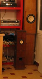
the enclosure design was found here :
La Petite Audiophile
I'll try the filter values , maybe will have to tweak as the enclosure is different
regards
dondiba
the enclosure design was found here :
La Petite Audiophile
I'll try the filter values , maybe will have to tweak as the enclosure is different
regards
dondiba
Attachments
Hi,
That box calculates to nearer 30L and a vent tuning around 45Hz.
I'd convert it to a FAST (full range assisted).
rgds, sreten.
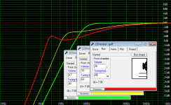
Response shown is without taking baffle step into account.
Try http://sound.westhost.com/bafflestep.htm
with limited power, increase its range if needed.
That box calculates to nearer 30L and a vent tuning around 45Hz.
I'd convert it to a FAST (full range assisted).
rgds, sreten.
Response shown is without taking baffle step into account.
Try http://sound.westhost.com/bafflestep.htm
with limited power, increase its range if needed.
Attachments

Last edited:

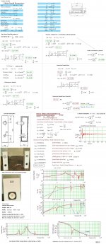
Hi,
Above is the simulated ripple of a little over 8" wide baffle, with a 5" driver
and rounded edges. In your case ripple will be more due to the straight
edges and the use of a smaller driver (that increases ripple).
You might be looking at about 12dB gain, 100Hz to 1KHz, taking
into account some room gain, nearer 15dB anechoic probably.
rgds, sreten.

FYI,
b🙂
Hi,
The MJK sim is more accurate than my simplistic box modelling,
indicating somewhat more bass output and more peaking.
It may sound like a wacky idea but adding a higher Q lower Fs,
higher Xmax driver in parallel as a 0.5 way driver might work well.
(You could of course just use another Fostex, but thats boring ...)
(The former something even Bjorno might be challenged to model .....)
This is cheap : Madisound Speaker Store (and great value).
Interestingly it has the same completely linear Xmax as the Fostex,
but due to the long coil and gap, will overload more gracefully I
assume. I reckon it will add ~ 10dB to maximum bass output.
But the inductor isn't : Madisound Speaker Store
Line the port with porous foam to detune and damp it somewhat.
1/4" foam would be a good place to start IMO.
You should also stuff the area behind the Fostex, to damp its
midrange and suppress the vertical resonant mode of the cabinet.
Whatever, you should end up with a a lot more bass and bass end
capability. The added driver should reduce the bass end peaking.
If done well the extra driver will suppress the fostex's limited excursion,
and the whole far exceed the starting point, for not much, fingers crossed.
rgds, sreten.
Last edited:
hi, why not ,
make a 2nd hole above the fostex' and closest as possible for a 2nd driver,
otherwise the precision of imaging would be impaired;
the 103fe and the aura are 8 ohms ,so in parallel the 'impedance' will be half, 4 ohms, i suppose, still drivable by a SS amp
could be fun but the enclosure is glued + screwed + braced very strongly...
so, i'll try to reduce the port first, it's easier ;-)
regards,
dondiba
Hi,
Lining the port reduces the tuning frequency, reducing its length
increases the tuning frequency and is generally a very bad idea.
There is little point mounting a 0.5 way driver above the main
driver. If the look appeals cut a hole above the Fostex for the
Fostex, stuff behind it. Enlarge the original hole for the Aura.
Chamfer the Fostex hole, the Aura hole is not so critical.
The drivers don't have to be particularly close at all for a 0.5 way.
The 0.5 way driver could be mounted pretty much anywhere below
the Fostex and the port, but if you like the visuals above go for it.
rgds, sreten.
Yes it will be 4 ohms in the bass, and 8 ohms in the mid/treble,
not a problem for most amplifiers other than naff IC amplifiers.
Last edited:
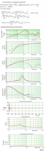
FYI:
The difference of using a 14 cm long port versus a 7 cm, both damped proportionally.
b🙂
Hi,
Your damping criteria is very obscure and hard to relate to practice.
Whatever number your playing with there seems no related practise.
I can't see the system the two cases are applicable to.
Lining a 70mm port with 6mm foam will reduce nominal diameter
to about 60mm and damp port modes. I can't see how you can
model this, I do it and it works well quite often. 1 cm foam in a
70mm port ~ detunes by half an octave, but can't be modeled
well as far as I know, its generally suck it and see, or measure.
rgds, sreten.
Last edited:
reducing its length
increases the tuning frequency and is generally a very bad idea.
you say generally a bad idea ?
what is your reason for saying that ?
I have often found a shorter port to sound better
cant say the same about making it longer
but Im only talking about very smaller changes
putting foam in a port is way too unpredictatble
unless its hard foam
but sometimes light stuffing with acoustic material works well
but then its really not ported any longer
but actually I have had positive result with placing smaller pieces in some areas of the port
I have no idea what happens, but it works well, sometimes
Hi,
Your damping criteria is very obscure and hard to relate to practice.
Whatever number your playing with there seems no related practise.
I can't see the system the two cases are applicable to.
Obscure 😀 See*
Lining a 70mm port with 6mm foam will reduce nominal diameter
to about 60mm and damp port modes.
What Port modes?. I see only quarter-wave modes related to the entire length of the airways where the port contribution is minimal.
I can't see how you can
model this,
It can easily be modeled by using suitable acoustical engineering
methods. The math can for example to be found here:
http://grputland.com/files/thes.pdf
I do it and it works well quite often. 1 cm foam in a
70mm port ~ detunes by half an octave, but can't be modeled
well as far as I know, its generally suck it and see, or measure.
I have access to the appropriate tools for this but showing these here is way above my commitment to help DIY:ers.
* Rather the opposite, I submitted all the numbers needed for an successful damped box/damped port design, here is more:
Select (dedicated for speaker use) a lump of modern ordinary fibrous damping material with the given weight of~ 1gram for a 7 cm long port.
Compress or tear the fibers apart in order to fill the entire volume of the port.
By doing so: This would correspond to a ~ density of ~0.2 kg/m^3.
Secure both sides by using an insect screen or similar.
The fiber tangle will stay and act as a flow resistance much like the 'Scan-Speak Flow Resistance Vent'.
The wider the Port diameter is compared to the port length, the better the linearity is expected to be for this arrangement.14 cm===> 7 cm is a good way to start with.
The airflow in the port is IMO/IME very small and already as a precondition, (pre-)filtered through the entire enclosure= a fill of denser stuffing in the box, thus only a near laminar flow is expected in the port.
Look at the magnitude of the port air velocity.
Considering this case(design): Your suggestion using port wall drag coefficients is IMO only a first step to consider if much higher port velocity exists and if the box were only lined at the walls for defeating internal reflexes.
b🙂
Last edited:
- Status
- Not open for further replies.
- Home
- Loudspeakers
- Full Range
- baffle step compensation, zobel, notch filter