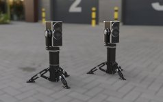
I have a goal to make super lightweight 'gear' using composites. Currently a Purifi 6.5 2-way is of interest. Having drafted several versions, this one (attached) is going in a direction to my liking, albeit the reasons are more to do with aesthetics.
The baffle design was meant to mitigate diffraction, but in hindsight I can see possible reasons that it may not do what's intended. I lack experience as to how well, or poorly, the baffle will perform and I don't have any way to measure it. The mid/tweeter housing extends from the plate 3/8" and has a 60deg. draft. Surrounding the housing, the flat plate portion is recessed 1/16", to be fitted with felt of similar thickness.
Furthermore, the dome tweeter is recessed to approximately midplane of the Purifi cone and is in close proximity, flowing into the curvature lines of the mid in a waveguide fashion. I have read many times that driver distance, the closer the better, is important. However, the simple 2-way systems I have seen do not usually manage to pack the tweeter as close as I have done here. I managed to make it fit, but I again have no clue if this is detrimental.
Any calibrated eyes out there to weigh in? On the one hand, I'd like optimal performance, but I don't know if I'm overthinking an nonissue. I am happy with it stylistically though...
Attachments

There is evidence that edge diffraction is an issue. Those who have or have made speakers with rounded edges say the speakers become harder to locate aurally.
From what I gather, driver separation will play a role there too, and I definitely covered that base. If done correctly, that is.
The raised driver grouping is loosely based on the teardrop style of some of the b&w designs. It's somewhat of the beginnings of the teardrop that gets sliced off. The waves that do reach the flat plane will meet the felt, which continues until the edge of the baffle, albeit to a thin metal edge. If that final edge is still an issue, I was thinking the felt height could be raised above that line.
If I'm understanding the problem correctly, the waves want to 'roll' along the flat surface until the edge is reached and diffraction occurs. With the felt, or whatever surface treatment, even though the hard edge is still there, that flat section leading up to it will hopefully do enough work that the effect is minimal.
If the final hard edge is still the issue, I have also tinkered with ideas to chop it up in ways that break the surface up.
Attachments
The baffles you have will diffract a significant amount. A circle is not a great shape.
dave
Yes, I had just read that once I finished up the design lol. So you are more concerned with the immediate raised grouping and less so about the edge of the plate?
There might be some options to break up the edge around the driver group, or maybe make it more eccentric. The circle is sort of a uniform focus feature for diffraction is one way I've heard it described.
It depends whether you are concerned primarily about the effect of edge diffraction on the frequency response or the effect of the secondary sources on imaging.
Imaging would probably take priority if there was a divergence in terms of what works better.
It's worth mentioning that this project went into the weeds on this because I wanted to try out that Purifi driver. Given it's unique properties, I wanted to tailor it's particular advantages, hence the baffle rabbit hole.
It's worth mentioning that this project went into the weeds on this because I wanted to try out that Purifi driver. Given it's unique properties, I wanted to tailor it's particular advantages, hence the baffle rabbit hole.
Dealing with the edge diffraction helps with both issues. Varying the distances to a sharp baffle edge just helps smooth the response.
The nature of the diffraction changes as frequencies become “small” compaired to the features of the box.
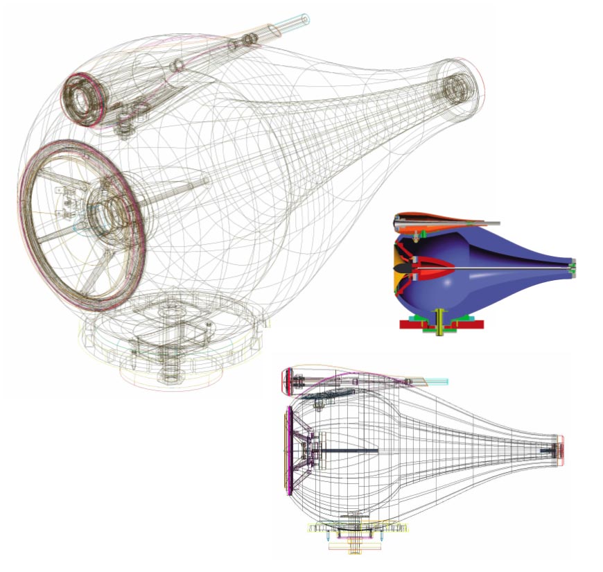
The teardrop shaped nautilus eclosure is large enuff to work at mid frequencies including the 2 pi to 4pi transition.
Your protruding features will only have an effect at the highest freuencies. You want smmmoooothh, gradual shapes (relative the frequency of interest).
dave
The teardrop shaped nautilus eclosure is large enuff to work at mid frequencies including the 2 pi to 4pi transition.
Your protruding features will only have an effect at the highest freuencies. You want smmmoooothh, gradual shapes (relative the frequency of interest).
dave
I'll have to do some reading on the 2pi/4pi because that one has flown over my head more than once. But in general I'm picking up what you mean about big n smoooth.
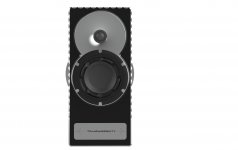
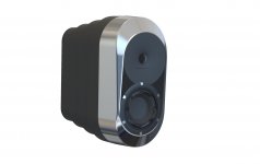
Earlier versions of the baffle project took that concept to the logical extreme and it sounds like your comments would concur with those attempts.
Something along these lines. Would you expect this smoothed version to sound better?
Earlier versions of the baffle project took that concept to the logical extreme and it sounds like your comments would concur with those attempts.
Something along these lines. Would you expect this smoothed version to sound better?
Attachments
Hehe 😛
Yeah, maybe I'm better off saying 'realistic extreme' lol.
To be honest, even that project is tame in the audio world!
Yeah, maybe I'm better off saying 'realistic extreme' lol.
To be honest, even that project is tame in the audio world!
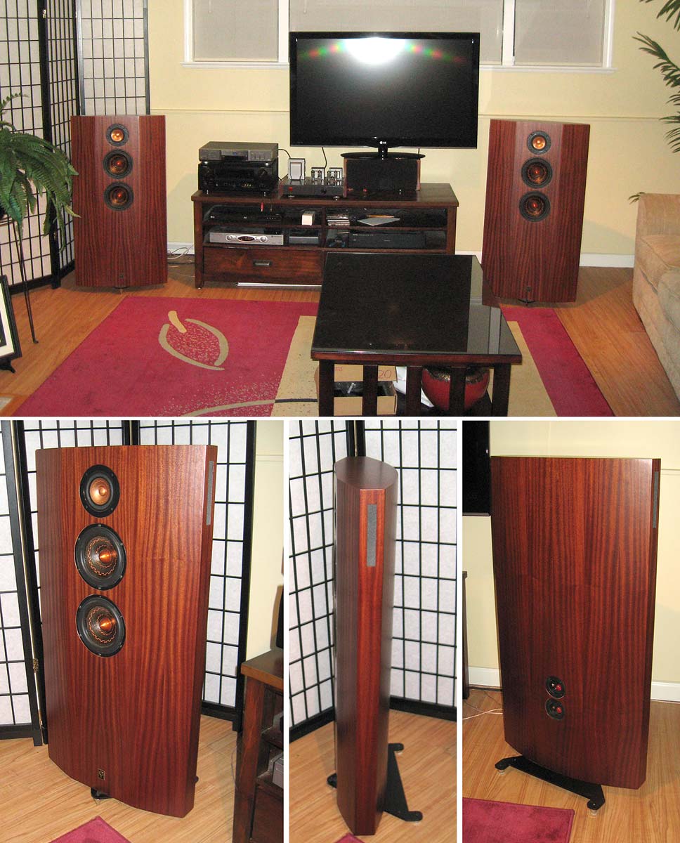
A little surprised nobody mentioned the stands themselves. The mounting ought to be below only and as small a footprint as possible ... including the connecting pipe/upright.
That is “sharp” at the edges.
Curves need to really be 3-4” in radius to be effective at amything but the highest frequencies. No sharp edges. What sharp means depends on the frequency you are talking about.
What you have shown so far reminds me of some of the molded baffles on big boomboxes solely to look impressive or different.
dave
A little surprised nobody mentioned the stands themselves. The mounting ought to be below only and as small a footprint as possible ... including the connecting pipe/upright.
Unless it is flat and extends the baffle to the floor… at that point you might as well push all the walls to the floor, lose the stands and fill the empy box with sand or another woofer.
dave
Hehe 😛
Yeah, maybe I'm better off saying 'realistic extreme' lol.
To be honest, even that project is tame in the audio world!
🙂 Chamfers can be very effective, a series of 30 degree chamfers are almost as good as a curve. This is a useful toy to get a feel for how waves behave Ripple Tank Simulation
Glad you brought that up because I haven't even considered what effect it might have. It would be pretty easy to directly attach the cabinet to the pole at the bottom. The tripod is a separate project that is adapted to the speakers and I was thinking it would be a cool feature to have some sort of tilt adjustment. Solve one problem only to create another....
Yes, at LF the bumps are unseen and a chamfer can provide a greater effective radius.
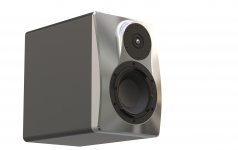
These started out as a 30° chamfer leading into a 45° chamfer, Chris looked at the drawing and said, “time to play with full curves and vacuum bags”.mg
This used the same technique in the midTL. Just a thot experimrnt. And the front top corners of the bass box should be sliced off to reduce diffraction of the exposed top edge.

dave
These started out as a 30° chamfer leading into a 45° chamfer, Chris looked at the drawing and said, “time to play with full curves and vacuum bags”.mg
This used the same technique in the midTL. Just a thot experimrnt. And the front top corners of the bass box should be sliced off to reduce diffraction of the exposed top edge.
dave
Attachments
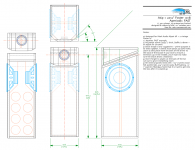
For whatever reason I have assumed that a narrow/deep cab performed better than a wide/shallow one. It looks like that Purifi unit want's about 25 liters and I plan on using a passive radiator. All said, it's a pretty small box; again, a driving force behind this project is to make it extremely lightweight and portable, but I still want to squeeze performance into it.
The planned baffle footprint is 8" wide by 18" long by 2" thick. This is to do with material availability, aka I have access to plates that size for cheap 😉
HOWEVER, IF super wide/shallow is the better geometry, I am happy to switch gears, as that is a far easier approach than chasing down every last edge due to the above mentioned footprint constraints. Under consideration...
- Home
- Loudspeakers
- Multi-Way
- Baffle Design....Diffraction and Crammed Tweeter?