Hello everybody,
in the following of this thread :
An advice for a SS amp to suit a Pass3x ?
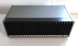
I found a Quad 405 to go with my Pass3x. It's a 405-1 born in April 1980. It was tested and it works, but the sound isn't very nice...

Nothing was changed in since it was made, so to use it I have to change capacitors, on the boards and the 2 big blue, very swollen.

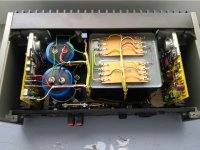
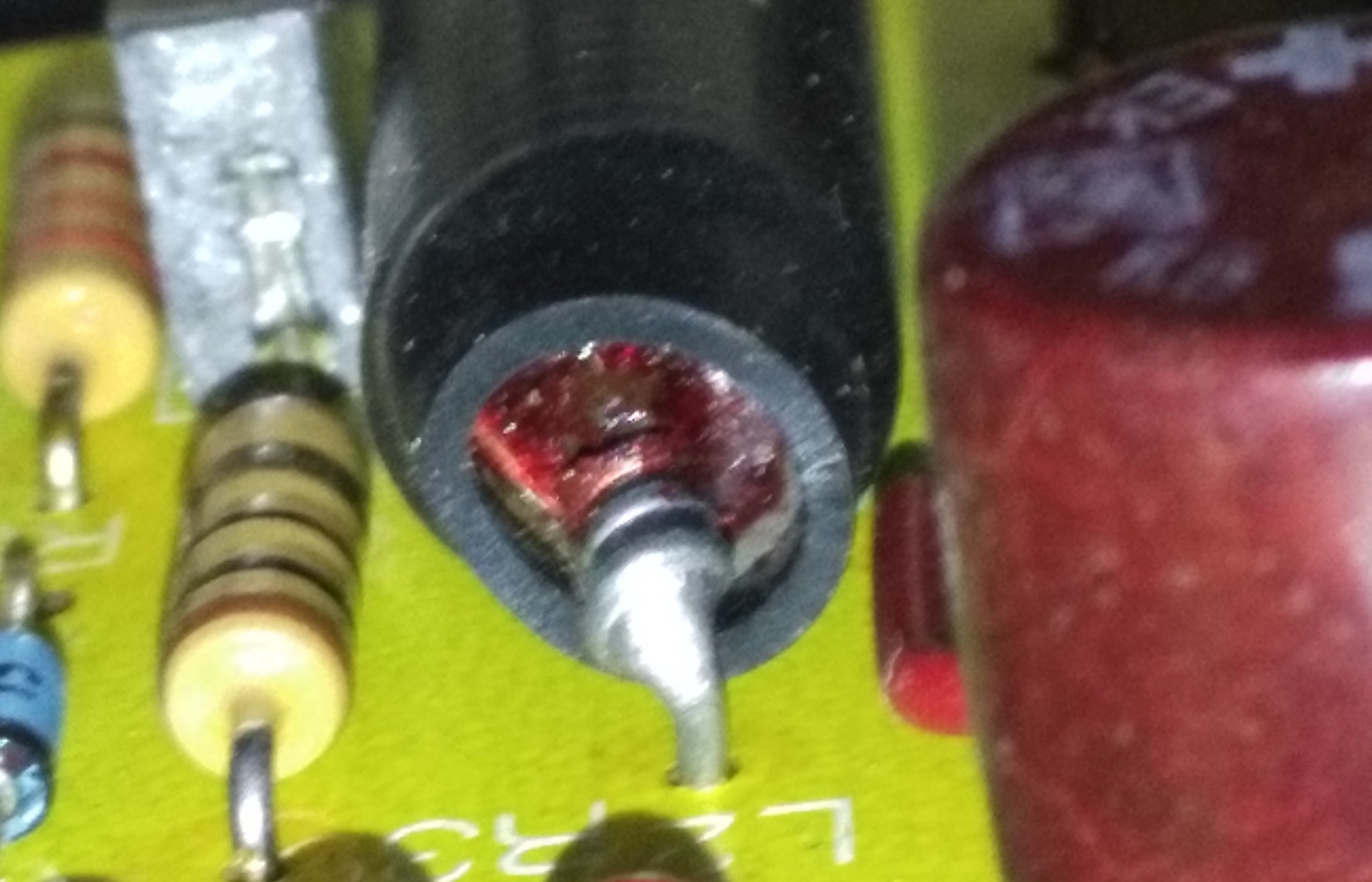
I could see that, on one board, one inductor, L2, suffered. Can it be because of the bad condition of the capacitors ? The electrolytic capacitor on the boards are in very bad conditions, some are cracked on the surface, they flee and very small bubbles of material can be seen along the crack. I couldn't read anything here about these inductors on Quad 405 boards.

I choose a non-modified amp to be sure of that to do on it, and because I just want to service it, I don't want something-other-than-a-405, I want to keep it as genuine as possible.
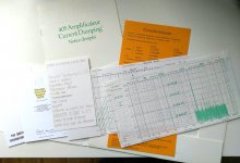
My amp was sold with all the litterature of the french importator: the manual, the 4-years warranty, and, interesting, all the measures made on MY amp. This is not so common with a 37-years old amp.

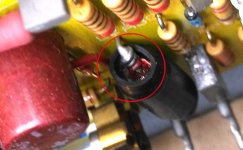
An idea about this inductor ? I will change it, of course, but do you see why it is so damaged ?
(And sorry for my english !! 🙂
in the following of this thread :
An advice for a SS amp to suit a Pass3x ?
I found a Quad 405 to go with my Pass3x. It's a 405-1 born in April 1980. It was tested and it works, but the sound isn't very nice...
Nothing was changed in since it was made, so to use it I have to change capacitors, on the boards and the 2 big blue, very swollen.
I could see that, on one board, one inductor, L2, suffered. Can it be because of the bad condition of the capacitors ? The electrolytic capacitor on the boards are in very bad conditions, some are cracked on the surface, they flee and very small bubbles of material can be seen along the crack. I couldn't read anything here about these inductors on Quad 405 boards.
I choose a non-modified amp to be sure of that to do on it, and because I just want to service it, I don't want something-other-than-a-405, I want to keep it as genuine as possible.
My amp was sold with all the litterature of the french importator: the manual, the 4-years warranty, and, interesting, all the measures made on MY amp. This is not so common with a 37-years old amp.
An idea about this inductor ? I will change it, of course, but do you see why it is so damaged ?
(And sorry for my english !! 🙂
Attachments
If you can se clearly bad caps, then, at first, replace all of them. In a first instance, the inductor can be replaced by a short piece of wire, until the rest of the amplifier is properly operative.
The value of the inductor is critical for the correct operation of the 'current dumping' output stage. Together with the compensation capacitor in the class-A stage, it forms part of the frequency-dependent bridge from which the negative feedback is derived.
Have a study of some of the articles which appeared in 1975 when the 405 came out. The circuit operation is more complex than first appears!
Have a study of some of the articles which appeared in 1975 when the 405 came out. The circuit operation is more complex than first appears!
Oh, thank you Osvalso.If you can se clearly bad caps, then, at first, replace all of them. In a first instance, the inductor can be replaced by a short piece of wire, until the rest of the amplifier is properly operative.
Yes, the amp works, but the caps are 37 years old too, and I'm convinced what the sound will improve a lot after recaping it. I didn't power it too long time, because I was afraid about the health of the 2 big blue !
I was wondering if the condition of this inductor is a consequence of the bad capacitors, because I didn't read anything about these inductor L2 in the forums. But yes, recaping it is the first thing to do.
Hello Ouroboros, and thank you for your precisions.The value of the inductor is critical for the correct operation of the 'current dumping' output stage. Together with the compensation capacitor in the class-A stage, it forms part of the frequency-dependent bridge from which the negative feedback is derived.
Have a study of some of the articles which appeared in 1975 when the 405 came out. The circuit operation is more complex than first appears!
Do you know what can make this inductor so damaged ? I always read about the caps to change in this amp, but nothing special about the inductors...
Why do you think the inductor is damaged ? (photos are very difficult to interpret when dealing with something like this)
The inductor carries all of the amplifier driving current to the speaker, but it will be only around 3uH, so it will not suffer any thermal stress, as the wire is quite thick.
The amplifier will work with the inductor replaced by a piece of wire, but the high-frequency distortion will be a lot worse.
The amplifier will work with the inductor replaced by a piece of wire, but the high-frequency distortion will be a lot worse.
Well, I'm not sure, but the end of this inductor doesn't look very clean... When I see the close-up, I'm not very confident.Why do you think the inductor is damaged ? (photos are very difficult to interpret when dealing with something like this)
It's a 3uH, 9A, dadaelectronic sells it, so I will change it, for precautions.
Attachments

The inductor carries all of the amplifier driving current to the speaker, but it will be only around 3uH, so it will not suffer any thermal stress, as the wire is quite thick.
The amplifier will work with the inductor replaced by a piece of wire, but the high-frequency distortion will be a lot worse.
This is why I suggested that the guy replace all bad caps, and leave the inductor to the last step. He can do the amp work pretty fine without it, and when all test has been finished, and the operation is satisfactory, place a new inductor, or rewire it. It appears to be few turns, so is a kind of 1 or 2 minutes to rewind it at hand.
Yes Osvaldo, that's what I'll do. I HAVE TO change all the electrolytics, so I wille change the two L2 in the same time.This is why I suggested that the guy replace all bad caps, and leave the inductor to the last step. He can do the amp work pretty fine without it, and when all test has been finished, and the operation is satisfactory, place a new inductor, or rewire it. It appears to be few turns, so is a kind of 1 or 2 minutes to rewind it at hand.
But nothing else. Oh, yes, I will reduce the imput sensitivity to 1,5v, this amp is bought to go with a Pass3x tube preamp, equiped with a buffer to feed the 20kohm imputs on the Quad. 🙂
I work in repairing industrial equipment of various kinds, in a small company the give services to bigger ones, some local, other international. In almost all equipment we repair, the first thing I do when I receive an unknown device, is to power it from an adequate power supply current limited (If 24V, from a bench PSU, if from 220V, with a lamp in series with the DUT, and if 3 phase, from a special device with 1ea 300W filament lamp in series with each phase. This is to see the initial state of the DUT. After disassemble it, the first to do is replace all smaller electrolytics. Mainly those of the starting of the SMPS (Usually 100µF 25/35V). When the DUT starts, then the second job is to recap almost entirely, excepting when the caps are big (For example, large caps in frequency converters for 3 phase motors). I can assure that 98% of the failures of an electronic device is from bad caps (Old, leaky, degraded, shorted, open, or the like). So, it is a good starting point to recap all the set. Pay attention to the polarity. Try to replace 2 or 3 per time, firing the set in between. If the thing goes wrong, you are sure that one of the lasts is the error in. Don't replace all of them simultaneously. Also, use a limited power supply, like a lamp (filament, not led nor fluorescent) in series with the mains, preferably in the live wire. If the lamps bright too much for a given power drain in the set (I use a lamp 10 times the expected power requirements of the DUT), switch it off immediately and re-look the last part of the job. A reversed cap, a short with a piece of solder, etc. Use a mirror or a lens if necessary.
Good luck.
Good luck.
Well, I'm not sure, but the end of this inductor doesn't look very clean... When I see the close-up, I'm not very confident.
It's a 3uH, 9A, dadaelectronic sells it, so I will change it, for precautions.
I would be very very surprised indeed if there were any issue with it tbh.
Are the output transistors original ? and do all parts look the same between channels ? That is a good guide as to whether the amplifier has any hidden history. If they are all original then I would be even more certain that the part was OK.
And be sure to replace all those ROE encapsulated electrolytics.
Thank you VERY MUCH for these advices !! I will follow them!I work in repairing industrial equipment of various kinds, in a small company the give services to bigger ones, some local, other international. In almost all equipment we repair, the first thing I do when I receive an unknown device, is to power it from an adequate power supply current limited (If 24V, from a bench PSU, if from 220V, with a lamp in series with the DUT, and if 3 phase, from a special device with 1ea 300W filament lamp in series with each phase. This is to see the initial state of the DUT. After disassemble it, the first to do is replace all smaller electrolytics. Mainly those of the starting of the SMPS (Usually 100µF 25/35V). When the DUT starts, then the second job is to recap almost entirely, excepting when the caps are big (For example, large caps in frequency converters for 3 phase motors). I can assure that 98% of the failures of an electronic device is from bad caps (Old, leaky, degraded, shorted, open, or the like). So, it is a good starting point to recap all the set. Pay attention to the polarity. Try to replace 2 or 3 per time, firing the set in between. If the thing goes wrong, you are sure that one of the lasts is the error in. Don't replace all of them simultaneously. Also, use a limited power supply, like a lamp (filament, not led nor fluorescent) in series with the mains, preferably in the live wire. If the lamps bright too much for a given power drain in the set (I use a lamp 10 times the expected power requirements of the DUT), switch it off immediately and re-look the last part of the job. A reversed cap, a short with a piece of solder, etc. Use a mirror or a lens if necessary.
Good luck.

Yes, all the output transistors are genuine Toshiba 2SD424, printed in red with the old Toshiba style ; and under :I would be very very surprised indeed if there were any issue with it tbh.
Are the output transistors original ? and do all parts look the same between channels ? That is a good guide as to whether the amplifier has any hidden history. If they are all original then I would be even more certain that the part was OK.
And be sure to replace all those ROE encapsulated electrolytics.
R *09
You think all is ok with this inductor ?
Oh, one question : I could read that le LM301 has lived, and I can find easily replacement OP, 100% compatible, giving a better sound quality.
Is there I chip I can use in place of the LM301, without any change of the components around it ?
Well, I'm not sure, but the end of this inductor doesn't look very clean... When I see the close-up, I'm not very confident.
It's a 3uH, 9A, dadaelectronic sells it, so I will change it, for precautions.
how is the condition of pcb trace under the inductor?
Yes Osvaldo, that's what I'll do. I HAVE TO change all the electrolytics, so I wille change the two L2 in the same time.
But nothing else. Oh, yes, I will reduce the imput sensitivity to 1,5v, this amp is bought to go with a Pass3x tube preamp, equiped with a buffer to feed the 20kohm imputs on the Quad. 🙂
If the inductor still makes contact, I wouldn't replace it.
By the way, by putting series resistors in the DIN plug you can reduce the input sensitivity, reduce the noise at the output and increase the input resistance without having to change the amplifier's circuitry at all.
Yes, all the output transistors are genuine Toshiba 2SD424, printed in red with the old Toshiba style ; and under :
R *09
You think all is ok with this inductor ?
Oh, one question : I could read that le LM301 has lived, and I can find easily replacement OP, 100% compatible, giving a better sound quality.
Is there I chip I can use in place of the LM301, without any change of the components around it ?
Yes, I honestly think all is OK with the inductor.
Having the original transistors in place suggests the amp has never failed in such a way to pass high current through that part... and even if it had I'd still bet the part would be OK.
Quad changed the LM301 to the TL071 and that is still a good choice imo. The Quad service manual shows all the changes that occurred although I believe only the LM301 and TL071 were ever used officially.
Another to consider would be the OPA604.
Feedback bridge
Very good explanation on how the (critical) feedback bridges works:
Quad 405-2 upgrades
by the way: agreed with others members, the inductor looks fine!
Very good explanation on how the (critical) feedback bridges works:
Quad 405-2 upgrades
by the way: agreed with others members, the inductor looks fine!
Hello,how is the condition of pcb trace under the inductor?
No mark of heat on the pcb at all.
Last edited:
If the inductor still makes contact, I wouldn't replace it.
By the way, by putting series resistors in the DIN plug you can reduce the input sensitivity, reduce the noise at the output and increase the input resistance without having to change the amplifier's circuitry at all.
Hello Marcel,
VERY interesting !! On an other thread, I was advised to use a buffer at the output of the Pas3x preamp, to make the valve preamp usable with the Quad 405. This kind of buffer : http://www.ebay.com/itm/Dual-OP-Amp-Board-Preamp-DC-Amplification-PCB-for-NE5532-OPA2134-OPA2604-AD826-/112419060034?hash=item1a2cb2b942:g7IAAOSwfpVZJta1
with a DUAL fet input op amp on this board (OPA2604).
Do you think really that a simple resistor, at the input of the 405, will resolve the problems of both the input sensitivity, and the imput impedance ?
- Status
- Not open for further replies.
- Home
- Amplifiers
- Solid State
- Bad condition of an inductor in a Quad 405