Hi All,
I need some advice here. Well, I have just brought up an amp that I built. It is out of "Silicon Chip" magazine and is rated at 500W into 4 ohms. It wants 80V rails but my PS gives 68VDC after filtering, no load. My filter caps are 10,000uF at 100V.
Well, it sounds great and with a lot of power. Absolutely no hiss or hum from this one.... WOW, a dream come true.... Anyway, I wanted these for use on my subwoofers and was testing in the sub region, way sub region, 18-25Hz and it happened.... KER-POW!!! One of the filters vented. I actually have 20,000uF of filter, 2X 10,000uF. Since there was probably only 60V of rail, at that load, the only thing that makes sence is reverse voltage going back to the power supply.
I am running a 12in. Shiva driver in a 4+ CUFT box with a 15in. passive radiator directly opposite. The box is massive with 1.5in thick MDF on all sides. It weighs over 150lbs and at 18Hz, the box was rocking back and fourth by an inch or so.
The amp is OK! I use 6X 2SA1943 and 6X 2SC5200 in the output stage. Today, with the lower supply listed above, I measured 240WRMS into 8 Ohms, 360WRMS into 4Ohms and over 540WRMS into2 ohms but 2 Ohm test was very short as the specs only talk about 4 Ohm minimum. I drove a resistive load with a sine wave input and all was OK, even at 10 HZ! I think the driver did it to my poor caps.
Can this be avoided in the future and how do I accomplish this? Is this what happened? or is it something else?
Please, someone, H E L P!!!!
Chris
Were these caps surplus?? I t helps to "form" them first. You can do that by putting a large value resistor in series with the cap and a DC supply.
Jocko
Jocko
was this the article posted quite a few years back>???
The voice coil heating up at 10 HZ will do that...LOL
DIRT®
The voice coil heating up at 10 HZ will do that...LOL
DIRT®
Diode
Do you have a copy of the whole article from Silicon Chip?If you have is it possible to furnish us one.
MGR
Do you have a copy of the whole article from Silicon Chip?If you have is it possible to furnish us one.
MGR
/opinion
...you exceeded the max ripple current by a fair degree, ******* off the cap.
Ya need some serious healthy caps in there to handle the current you are expecting to get out.
$$$
/end opinion
...you exceeded the max ripple current by a fair degree, ******* off the cap.
Ya need some serious healthy caps in there to handle the current you are expecting to get out.
$$$
/end opinion
Caps were not surplus but may have needed to be formed. They came out of a Peavey amp with the same transformer. They are from a model PV.75K. If the ripple was a problem and I need better caps, Where can I get some better ones at a reasonable cost? I realize that they will be 30+ dollars. The project calls for 40,000uF of filtering per rail. OUCH!
Silicon chip has told me not to post the write-up for copywrite reasons but they don't sell the back issues of the article anymore. I don't get it...... I don't have the the entire thing scanned but I can send it to your e-mail when I do. I have the schematic and parts list scanned only, right now.......
Joe, What do you mean about the voice coil heating up? Sounds interesting........
Any other info on this phenomenon will be greatly appreciated.
Chris
There was a thread in the archive regarding the use of power supply
capacitors near their voltage rating, ie,
if it's rated for 75V most people used
the cap at 70V-75V without problems.
I'm looking at some 100V capacitors
and plan to run them at 92V - 94 V
and wondered if it's to close to threshold?
Perhaps it's an issue of true ratings or did marketing getting involved in
the creation of the capacitor specs?
Suppose a capacitor is really only
capable of 60V operation, but the
marketing people force a 75V label
to be placed on the cap ?? / haha!
Or
Suppose a cap is design for 120v
and a 100v label is placed on
to maintain reliability ??
/hehe
Diode I was referring to that the voice coil reduces its resistance when the driver is driven to its excursion (resonant frequency at 10 hz) so basically the amplifier will see a lower impedance if it is driven long enough
electrolytic capacitors usually have a 20% factor built in to their working voltage....that is why you usally see two different voltages on larger caps "Working" and "Peak" voltage
I looked for the article and dont have it.....But I did come across an article in Electonics Now from a Oct 95 issue with a nice 700 watt amplifier with a switching P/S...a company called A and T Labs posted it
DIRT®
Hey Dirt,
Yeah, I can see that but I think that the amp should have failed and not the caps. What I need is a way to fix the problem. I still somehow think it was back EMF and the voltage fed back into the caps exceeded their voltage rating. With this logic, the amp should have failed too. I have never seen this except when the caps haven't been used for many years. That may have been the case also because these caps were in my bosses junk piles and I don't know how long...... It had to be something in the load as it was reactive. I used resistive loads at work and it worked fine at low freq. high power. The speaker seems to have had some kind of effect.
Chris
Diode,
Do you have a copy of the PCB design (foil and parts placement) for that amp?
I just wish you can send it via email.
ndijamco@edsamail.com.ph
JojoD
Do you have a copy of the PCB design (foil and parts placement) for that amp?
I just wish you can send it via email.
ndijamco@edsamail.com.ph
JojoD
Hi Diode,
what an irony... a diode may help. I have seen diodes used in some PSU schematics, after the regulation stage, parallel to caps to shunt any possible back-EMF to ground (usually in regulated supplies). The diode of course will only conduct should reverse bias voltage appear on the caps. Use large current ratings ;-)
Still since your blown caps are obviously not directly at the output, I can't see why any reverse bias should have reached them, but then again, 2 diodes (1 each rail) are cheap.
Besides back-EMF what may have happened is one of 2 things
1 - at heavy current draw you had sagging rails, and due to the low frequency the caps were fast enough to go through many 2/3 or 1/2 "full" charge cycles ... thereby overheating. So it may not have been excess voltage but excess temperature.
2 - heavy current draw itself, due to say a short circuit can damage a cap even if all other specs are respected.
You may be right! I already have diodes on the rails. They are seen in the schematic. We call them flyback diodes. The thing is, the power supply came out of a high power PA amp. I would figure that they would have blown in that application. I had a suggestion from a couple fellow techs today that if I had more caps in parallel, the ripple current would be divided better. I know that the weak link would be the weakest cap but the chances of that happening would be less, by default. I have to admit that I didn't have the 40,000uF in, I only had 20,000uF, which is only half the capacitance AND half the current paths. What do you think of that theory? I am currently slow charging the remainder of my caps. I put a variAC on the transformer and have them on 11VDC charge all night. I will raise it to 20V tomorrow and in 5V increments there after until my full rail voltage appears on them. I may run the variAC up higher than 110VAC input so I can get closer to 100VDC on the caps. I have no load though, just charging the caps slowly. I guess it will take me the better part of a week to do but I suppose it will pay off in the end. Thanks so much for all of the advice.
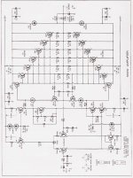
I will try to scan the board and layout but it will be a copy of a copy and I don't know the results. The problem is that they are on 11X17 paper and will have to be scanned in pieces. I'll do my best. It's a really simple layout except ALL of the transistors are in a long line. I wish they were in 2 rows, taking up half of the space. I really like the amp!!! No hiss or hum in mine. This, above all, is it's best point. They said it was a quiet amp and they were right!!!
Does anyone think Silicon Chip Magazine is being too inflexible to tell me that they had a problem with a 1996 project being posted even in part? They don't even have back issues of it and Dick Smith Electronics doesn't sell the kit any more. In my opinion, I don't see the problem. They were pretty vague except they said that they had a big problem with me posting it on the internet and told me not to do it. Silicon Chip is a great magazine though, I'm not slamming them in that way. I just don't agree with their position on this particular issue. Any opinions from you guys?
Chris
place a 2k 5 watt resistor on the caps for conditioning......I use clamp diodes also but before the caps and have outputs fused .it basicaly prevents destruction of the mess I make in the rest of the circuit
DIRT®
DIRT®
EchoWars said:/opinion
...you exceeded the max ripple current by a fair degree, ******* off the cap.
/end opinion
Diode said:I had a suggestion from a couple fellow techs today that if I had more caps in parallel, the ripple current would be divided better.
Everyone looks at voltage ratings of caps, and uF of the caps, but no one ever looks at RMS current ratings. I'm with EchoWars, it was probably a heating problem due to ESR and high currents.
Sometimes the best cap for the job isn't one cap, but many smaller caps in parallel. You may even find that you'll get more uF, and a higher RMS current for less $$ (Alwyas a good thing!).
Good Luck on the caps!
-Dan
p.s. I'd like to see that article, if you get it scanned 🙂
do you have any idea about what power level you where running at when the cap vented?
since you wrote that you where playing low frequency material, this increases ripple current in the capacitors more than high frecquency material. Ripple current is roughly equal to twice the output current, by some old rule of thumb that I have in memory, please correct me if I am wrong here.
A Rifa PEH200, 10000 uF, 100 V cap has a maximum ripple current at 15 A @ 85 C, a temperature easily reached with high ripple currents. And this cap is one of the toughest available. so a lesser cap could probably not take more than say 10 A@ 85 C
so, if you where playing out loud, I would be surprised that you overheated the cap beacuse of excessive ripple current, and hence venting. Also, aging of caps decreases ripple current capacity due to increase ESR.
It is possible to create a back emf from a passive crossover with several loudspeakers but it is not very likely.
what to do? Use higher grade caps, preferably rated at high temp and high ripple currents.
using multiple caps in parallell is an option , but it is important that ripple current is shared equal, otherwise the caps will "ripple" current between themselfes , even if output power isnt very large. sharing is influenced by PCB layout, wire lenght e tc. Quite complicated, thus.
good luck with your DIY, the amp looks promising, especially with the outputs you use.
/rickard
- Status
- Not open for further replies.
- Home
- Amplifiers
- Solid State
- Back EMF? caps vented...