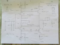
Theme and Variations on a BA-3 driver stage and BA-1 follower output stage
Before soldering this , thought it might be good idea to run it by the experts .
For the voltage gain driver stage , I have some
The Idss ~ 7.0 mA for the jFET's .
Is matching of the lateral MOSFET's required ?
With the jFET's biased at around 4.2 mA to 4.7 mA is this enough current to be able to effectively drive
the lateral MOSFET's . Is there a cook book equation people use for this ?
The lateral MOSFET's seem to be quite content with a bias = 100 mA
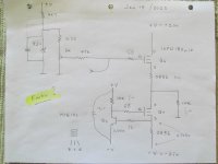
For BA-1 follower output stage , rather than trying to match up 6 x IRFP240 's MOSFET's
thought it would be easier to use singles of IXFN180n10 MOSFET's ( Ciss = 10,900 pF )
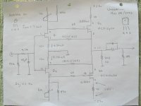
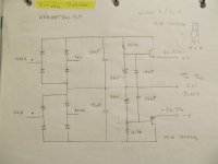
So here are the schematics , any advice would be appreciated before the soldering iron comes out .
( Or the hammer )
.
Before soldering this , thought it might be good idea to run it by the experts .
For the voltage gain driver stage , I have some
- 2sk246 BL and 2sj103 BL jFETs
- Exicon ECX10n20 and ECX10p20 lateral MOSFET's ( Ciss = 500 pF )
The Idss ~ 7.0 mA for the jFET's .
Is matching of the lateral MOSFET's required ?
With the jFET's biased at around 4.2 mA to 4.7 mA is this enough current to be able to effectively drive
the lateral MOSFET's . Is there a cook book equation people use for this ?
The lateral MOSFET's seem to be quite content with a bias = 100 mA
For BA-1 follower output stage , rather than trying to match up 6 x IRFP240 's MOSFET's
thought it would be easier to use singles of IXFN180n10 MOSFET's ( Ciss = 10,900 pF )
So here are the schematics , any advice would be appreciated before the soldering iron comes out .
( Or the hammer )
.
Attachments
Concerning matching p and n type lateral MOSFET's , in the output of the driver stage , there is a discussion about this topic right here .
https://www.diyaudio.com/community/threads/matching-l-mosfets.30917/
The late Charles Hanson wrote :
" Don't try to match the P-channel devices to the N-channel devices. Just match each polarity to itself. "
Christer asked : " Could you please elaborate a bit on why you make this recommendation ? "
Charles Hanson answered : " There are a couple of reasons for this. The first is a practical one, in that it is almost impossible to match Vgs across both polarities. I suppose that you could do it by throwing away 60% to 80% of the parts you buy.
The next reason is that the N-channel parts have a lower output conductance than the P-channel parts. This is especially true for the Toshiba brand MOSFETs (as opposed to the Magnatec clones which are much better in this regard). This means that whatever reading you get will depend slightly
on Vds for the N-channel parts, but significantly for the P-channel parts. So you could only match them for one specific Vds condition.
But guess what? When you are running them as followers in an audio amp, Vds is constantly changing!
Besides, about the only thing you are losing is a slight DC offset by not matching them. This is easily compensated for elsewhere in the circuit. "
" Magnatec = Exicon "
.
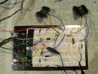
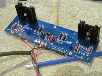
Here is the driver stage with a few resistor changes .
I soldered it on an F5 v3.0 board .
The pin out on the Exicon lateral MOSFET's is not the same as an IRFP240 .... the S and D are switched .
So I rotated the lateral MOSFET's a 180 degrees , and drilled a hole for the gate .
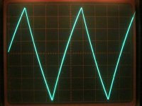
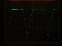
f = 20 KHz for the scope trace .
Note without the P3 trimmer in the middle , Vout is slightly asymmetric .
A DMM measurers Vout = 0 Vdc , but the scope shows the amplitude of the bottom half of the waveform is larger than the top.
Is this harmonic distortion ?
I'm wondering if this would make a great headphone amp ?
With the output biased at 100 mA , there is no issue holding the heat sinks .
As I recall , 50oC is about the limit of what a person can hold .
If 45 mA of the BA-3 can drive 6 x IRFP240 's of the BA-1 follower output stage
Then 100 mA should have enough gusto to drive the Ciss = 10.9 nF of a IXFN180n10 .
.
I soldered it on an F5 v3.0 board .
The pin out on the Exicon lateral MOSFET's is not the same as an IRFP240 .... the S and D are switched .
So I rotated the lateral MOSFET's a 180 degrees , and drilled a hole for the gate .
f = 20 KHz for the scope trace .
Note without the P3 trimmer in the middle , Vout is slightly asymmetric .
A DMM measurers Vout = 0 Vdc , but the scope shows the amplitude of the bottom half of the waveform is larger than the top.
Is this harmonic distortion ?
I'm wondering if this would make a great headphone amp ?
With the output biased at 100 mA , there is no issue holding the heat sinks .
As I recall , 50oC is about the limit of what a person can hold .
If 45 mA of the BA-3 can drive 6 x IRFP240 's of the BA-1 follower output stage
Then 100 mA should have enough gusto to drive the Ciss = 10.9 nF of a IXFN180n10 .
.
Attachments
Last edited:
To point out the test trace shown above is not a triangle wave - but rather its from a DIY RC audio test generator.
The signal rises and falls based on e .
The specs from a W4S DAC 2 say Vout (max ) = 2.6 Vrms ... using the unbalanced RCA output .
This DAC has an preamp output and digital volume control .
The system I plan on using this with is
W4S DAC 2 ==> tube buffer == > BA - 3 and BA - 1 amp ===> Speakers
This is why I pushed the voltage gain of the driver stage .
For the driver stage , measured with RL = 10 K and source resistors Rs = 10 ohms
Voltage rails = +/- 24.6 Vdc
Vin = 7.0 Vpp
Vout = 42 V
Av = 6.0 ( 15.6 dB's )
.
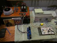
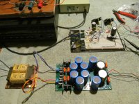
So here is a complete prototyped amp .
With a basic H/K 7600 CD player == > modded BA-3 and BA-1 == > B&W 110 speakers
and a basic CRC power supply, sonically its quite impressive.
Listening to Dave Brubeck's Time Out , it sounds very relaxed and yet dynamic.
The transient response of Paul Desmond's alto sax is very good .
In terms of audio equipment , listening to a piano concerto separates the sheep from the goats very quickly .
Lief Ove Andsnes performance and the recording quality of Mozart Piano Concerto No. 20 is pretty good .
aka The Vikings play Mozart . That's quite the piano he is performing on.
This is a really enjoyable amplifier . ... the current stage is only biased at 0.71 Amps , which I plan to push up to 1.26 Amps on the final amp .
The BA-3 driver stage measures fine at 1KHz at full gain .
but the scope shows it starts to struggle at near full gain at 20 KHz .
Reducing the source resistors to 2R2 would probably help .
However, the amp sounds so good I almost don't care .
.
Attachments
Last edited:
Very interesting project! Thanks for sharing the journey.
I particularly like using the F5 boards for the modified BA-3 front end. Nifty!
I particularly like using the F5 boards for the modified BA-3 front end. Nifty!
" I particularly like using the F5 boards for the modified BA-3 front end. "
Thanks for your support .
Concerning the F5 voltage gain stage , its unfortunate that the ECX10n20 and IRFP240 weren't pin for pin compatible.
Also note that with IRFP240's , the metal back is connected to the drain .
Where as with the ECX10n20's the metal back is connected to the source .
So with an F5 style of amp , the Exicon's need separate heat sinks .
Looking at the data sheet for the EXC10n20's , and thinking about a plotting a load line ,
running them at 100 mA is barely on the family of curves .
http://www.exicon.info/PDFs/ecx10n20.pdf
However , they sound great at 100 mA , so I don't know what to say about this .
I'd like to hear this F5 voltage gain stage set up as a headphone amp .
Also , think its best that the F5 driver stage has its own power supply , with ultra clean supply rails .
If ordering the Exicon MOSFET's from Profusion , consider shipping by Royal Mail .
I ordered them using the courier opinion and got dinged with a brokerage fee .
.

An advantage of the BA-3 voltage gain stage and its current stage , is that a separate power supply can be used
for each of the 2 stages.
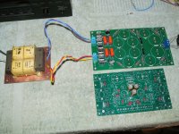
For the BA-3 voltage gain stage , one consideration is the Sigma 22 power supply , which is shown in the photo .
But from experience with line stage tube preamps ( low voltage 6gm8 ) , I know the combination of
Fo Felix DIY EMI filter === > Split Bobbin Transformer ===> Clipper Supply ==> 4th order LPF is very good .
So I'm going with what I know .
I highly recommend DIY'ers give a Fo Felix EMI filter a try .
A split bobbin transformer has the advantage of low capacitive coupling between the primaries and secondaries .
Hammond makes the 229 series which are very quiet .... but need a circuit board .
The clipper supply works by taking a pair of scissors , and just cutting off the top of the rectified waveform .
So any of the Hydro noise , at the rectified peak , is just cut right off .
Then this is all filtered by a 4th order ladder filter
.
for each of the 2 stages.
For the BA-3 voltage gain stage , one consideration is the Sigma 22 power supply , which is shown in the photo .
But from experience with line stage tube preamps ( low voltage 6gm8 ) , I know the combination of
Fo Felix DIY EMI filter === > Split Bobbin Transformer ===> Clipper Supply ==> 4th order LPF is very good .
So I'm going with what I know .
I highly recommend DIY'ers give a Fo Felix EMI filter a try .
A split bobbin transformer has the advantage of low capacitive coupling between the primaries and secondaries .
Hammond makes the 229 series which are very quiet .... but need a circuit board .
The clipper supply works by taking a pair of scissors , and just cutting off the top of the rectified waveform .
So any of the Hydro noise , at the rectified peak , is just cut right off .
Then this is all filtered by a 4th order ladder filter
.
Attachments
Concerning the clipper supply , to point out , the 2 Zener diodes should be matched
so that +Ve and - Ve output are reasonably close .
Also , one correction Vout ( 7.5 k load ) = Vz - Vbe
One question about having a power supply for the BA-3 ( or Mini Me F5 ) and another for the current gain stage ,
How does Vout behave , if the current gain stage , is powered up before the BA-3 ?
However, there is a DC coupling cap between the 2 stages . Plus the BA-3 powers up and down very symmetrically
around 0 Vdc . There are no wild DC swings from Vout when the BA-3 powers up or down .
So the whole set up in the photo attached measures beautifully .................... except .
When the Mini Me F5 is biased at 103 mA and Vout = 40 Vpp
there is about 4 mVpp of the test signal showing up on +Ve and - Ve right on the power supply output .
Yet each one of those power supply electrolytic caps on the ladder filter is 6,800uF
So with this supply , the signal is showing up a touch on the BA-3 supply rails .
.
Attachments
Looking at the data sheet for the EXC10n20's , and thinking about a plotting a load line ,
running them at 100 mA is barely on the family of curves .
http://www.exicon.info/PDFs/ecx10n20.pdf
However , they sound great at 100 mA , so I don't know what to say about this .
OK , so the answer to the issue of linearity for ECX10n20's is on the datasheet .
Looking at the transfer characteristics graph ( Gate Source Voltage vs Id )
Yfs = delta Vgs / delta Id
The transconductance starts to become linear when Id >= 100 mA .
.
- Home
- Amplifiers
- Pass Labs
- BA-3 and BA-1 variations