I have this sub, that has blown output fets and fuse..
I have replaced both fets, and to be on the safe side, I also replaced both opamps and Q610
I hooked up an amp meter on the fuse holder, and slowly brought up the voltage on a variac.
no sooner there is about +-6v dc on the rails, the current being drawn is through the roof..
There is still something not right.
‘I must confess, I have not seen this amp topology before, so I don’t know what to start looking for at the moment.
I really do need some guidance, maybe how it should work as a start.. it could give clues as to what is else is wrong.
- Does it need a load connected to work?
- What does Q605 actually do here? In conjunction with IC602.
- There are two BC601 marked on the circuit..one of them has a link
- And if I remove pin6 of IC601, no current is drawn..cool.. but obviously no output either
.")
Attached is a schematic, but can also be found on hifiengine.
I must confess, I have not seen this amp topology before, so I don’t know what to start looking for at the moment.
See Common Source Power Amplifier Using an Op Amp Driver Stage (link https://www.eeeguide.com/common-source-amplifier-using-an-op-amp-driver-stage)
Basically the final stage, the MOSFETs are driven by the IC601 current consumption in a more complex schematic where Q603 Q604 reduce the supply voltage for NJM 5534 (max voltage ±22V) to a voltage set by Zener diodes D601, D602 and the emitter current of Q603 Q604 (the current consumption of NJM 5534) which is (almost) equal with collector current goes trough R606 respectively R607 generating the command voltage for Q601 Q602.
If the current trough fets is high you can assume that the current through R606 or/and R607 is high for example if one of the D601 D602 is interrupted or one of Q601 Q602 is in short.
It should not blow the Fets without signal, without a load. R610 +R611 group is in parallel to the output.
- Does it need a load connected to work?
after a quick look, I would say I602 takes the out audio signal of IC601, rectify - making a DC voltage proportional with the audio output level which at a certain point make Q605 open and limit the audio input for IC601 (basically an audio limiter loop, to keep the maximum output level in check)
- What does Q605 actually do here? In conjunction with IC602.
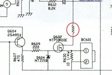
I would say you need to limit the current of Q601 Q602 so you can actually be able to power up without destroying anything and be able to measure the voltage on R606 R607, the voltage on IC 601 pins, ... My suggestion is add some resistors as in the attached pictures, something like 220 ohms (100 - 470) at a wattage that would hold when the power supply is applied on them. Some100W incandescent lights can be used, I don't have a variac, so when I have a blown fuse I put a 100W incandescent light instead of the fuse: without signal if everything is ok the light bulb will flash (until capacitors charge) at power-up then remain off. If there is a short the light bulb would be continuously on and the current would be limited to less than 1 A (valid in US where outlet voltage is 110V)I really do need some guidance, maybe how it should work as a start.
Attachments

Thank you the great explanation.. genius.See Common Source Power Amplifier Using an Op Amp Driver Stage (link https://www.eeeguide.com/common-source-amplifier-using-an-op-amp-driver-stage)
Basically the final stage, the MOSFETs are driven by the IC601 current consumption in a more complex schematic where Q603 Q604 reduce the supply voltage for NJM 5534 (max voltage ±22V) to a voltage set by Zener diodes D601, D602 and the emitter current of Q603 Q604 (the current consumption of NJM 5534) which is (almost) equal with collector current goes trough R606 respectively R607 generating the command voltage for Q601 Q602.
If the current trough fets is high you can assume that the current through R606 or/and R607 is high for example if one of the D601 D602 is interrupted or one of Q601 Q602 is in short.
but, I have already replaced q601 and 602.. they are not short.. and D601/602 are 15v zener.. I am not even getting that high for them to act as 15v zener.. they are not shorted either.
I could try and replace, but I didn’t see the point.
That is why I suggested adding the red circled resistors; so basically the idea is that we need to find a method to get somehow the power rails to a higher value (enough to measure something) without destroying anything, by limiting the current trough components that might blow up - the fets, and then it will be possible to switch from a brute force approach (start replacing components one by one until you find the problem) to an I can measure and with some logic thinking find the problem.I am not even getting that high for them to act as 15v zener..
Otherwise, we will keep guessing, examples of things that can make high current through fets
Q609 (shorted, leaking collector-emitter) remove Q609 and test with the variac
Q610 (interrupted collector)
VR601 interrupted
R606 or R607 interrupted
...
You said you can get the rails to ±5V ; what is the voltage on R606 and R607 then ?
Makes sense.
will do that.. all the Q have been tested , but that doesn’t mean they are not leaky..
as you say if brute force fix, there aren’t that many active components on this 😀
will do that.. all the Q have been tested , but that doesn’t mean they are not leaky..
as you say if brute force fix, there aren’t that many active components on this 😀
Some updates.. I got it running now, without blowing any fuses anymore.
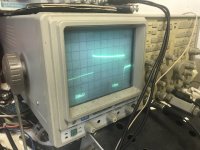
‘next issue is, there is a square wave on the output. Not sure what’s causing it, but I have verified what’s not causing it.
I’ve removed c605 and c607 from the path.. so the bottom feedback with the 4558 is ok.
The collectors of q603 and 604 shows the square wave pattern..and everything to the right of those.
there is correct voltage on the zeners as well.
the voltage on those collectors is on and off..
kinda of stuck now.. I can’t break the output feedback to pin 2 of the 5534, otherwise it will run away..
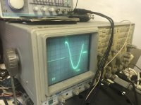
good news is, it’s passing a signal to the output, and it’s being amplified, all be it distorted due to the on/off of the fets..as in when the fets are in, there is clean signal.
‘next issue is, there is a square wave on the output. Not sure what’s causing it, but I have verified what’s not causing it.
I’ve removed c605 and c607 from the path.. so the bottom feedback with the 4558 is ok.
The collectors of q603 and 604 shows the square wave pattern..and everything to the right of those.
there is correct voltage on the zeners as well.
the voltage on those collectors is on and off..
kinda of stuck now.. I can’t break the output feedback to pin 2 of the 5534, otherwise it will run away..
good news is, it’s passing a signal to the output, and it’s being amplified, all be it distorted due to the on/off of the fets..as in when the fets are in, there is clean signal.
- Home
- Amplifiers
- Solid State
- B&W AS6 subwoofer..amp topology questions