Hi,
New frontier here. I have a set of B&W DM610i which I bought new in '95. Can't believe it has been that long. I want to rebuild / upgrade the crossovers with new capacitors. I have a basic knowledge of soldering, however, the electronics world is relative new.
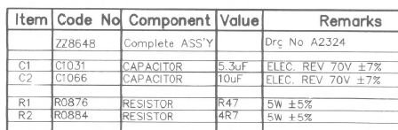
The factor crossover has Bennic brand. 1. 5.3 uf 70v 7%+/- and one 10 uf 70v 7%+/-.
I need / would like specific advice on replacements for these two capacitors. Finding a 5.3 is no easy. I know I could combine two to meet that value but would prefer one vice two.
I am powering these with a Quad 405 mk1 - upgraded with new components.
Has anyone done this or have any advice.
At your mercy. Thanks.
New frontier here. I have a set of B&W DM610i which I bought new in '95. Can't believe it has been that long. I want to rebuild / upgrade the crossovers with new capacitors. I have a basic knowledge of soldering, however, the electronics world is relative new.
The factor crossover has Bennic brand. 1. 5.3 uf 70v 7%+/- and one 10 uf 70v 7%+/-.
I need / would like specific advice on replacements for these two capacitors. Finding a 5.3 is no easy. I know I could combine two to meet that value but would prefer one vice two.
I am powering these with a Quad 405 mk1 - upgraded with new components.
Has anyone done this or have any advice.
At your mercy. Thanks.
If there is any benefit to this it might be reduced where the existing capacitor has resistance and inductance in series with it.
Without giving a straight answer it might be said that using either a 4u7+0u56, or 2x2u7 could be justified.
Without giving a straight answer it might be said that using either a 4u7+0u56, or 2x2u7 could be justified.
The Bennics would be electrolytics. I'm of the view of replacing polys with polys and lytics with lytics in passive crossovers, especially B&Ws.
I recently replaced my B&Ws of the same vintage in another thread and had somewhat similar issues with the lytics.
Mundorf makes e-caps at 1.0uF and 3.3uF. So you could parallel two 1.0uF and a 3.3uF to get that value. Kinda what I did in my setup.
Mundorf also makes e-caps at 10uF.
Note that they will be much larger than the OEM caps so make sure they can fit on the PCB and also fit within the cab.
There are cheaper alternatives but I'd be careful to look into ESR and DF for the old and new caps.
Have fun.
Does this work?
Mundorf E-Cap Plain 10uF 70VDC 50VAC
Mundorf E-Cap Plain 1.0uF 70VDC 50VAC x2
Mundorf E-Cap Plain 3.3uF 70VDC 50VAC
for each crossover?
Mundorf E-Cap Plain 10uF 70VDC 50VAC
Mundorf E-Cap Plain 1.0uF 70VDC 50VAC x2
Mundorf E-Cap Plain 3.3uF 70VDC 50VAC
for each crossover?
Does this work?
Mundorf E-Cap Plain 10uF 70VDC 50VAC
Mundorf E-Cap Plain 1.0uF 70VDC 50VAC x2
Mundorf E-Cap Plain 3.3uF 70VDC 50VAC
for each crossover?
Yes, but you should look at the exact dimensions of those caps to make sure that they will fit on the boards and that there are no clearance problems inside the cabs.
I would leave the resistors in place unless absolutely necessary. I had to replace mine because I could not solder the new caps to the board properly without doing so. Mine were wirewound in cement BTW.
I would measure the resistors and if within tolerance leave them alone. Replace the electros with electros of good quality. The ESR of the electros would have been factored into the original design. I do remember reading somewhere that if you replace electros with film caps you should add 1 ohm series resistance for every 10MFD. I'm not sure how effective this might be and I've never put it into practice. Food for thought.
I would measure the resistors and if within tolerance leave them alone.
Definitely. Though you may have to unsolder one of the leads on the resistor to get a correct measurement versus measuring it in-circuit.
It always helps to post the crossover diagram and a picture. Below from the service manual.
B&W Group North America Service & Support - Home
The 10uF is in series with a 4.7R resistor, so the ESR and hence type of capacitor shouldn't matter. So electrolytic or MKP.
The tweeter has an electrolytic 5.3uF and not much resistance at 0.47R, so changing it to a standard 5.6uF MKP (polypropylene) might entail changing the resistance. Say 1.5R if it sounds too bright, because electrolytics come with "free" series resistance around an ohm.
Since the capacitor is 7% tolerance, and always a bit vague in practise anyway, I wouldn't lose too much sleep over a 5% change in value. That will be inaudible. In practise 5% change alters crossover frequency by 2.5%. It's a square root relationship of inverse LC in a second order filter.
Attachments

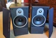
The B&W DM610i is an interesting speaker. It's actually a 4 ohm unit. Polycone bass and metal ferrofluid tweer.
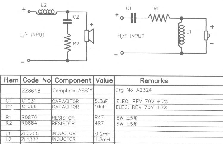
Since it's 4 ohm, crossover must be around 3kHz. If you were using 8 ohm units, you'd add 50% to inductance and resistances, and reduce capacitors by about a third. So the bass just has a bit of near-Zobel impedance correction.
Which is pretty much what works with most well-behaved 8" bass units. And polycones are the ultimate well-behaved and smooth units. 😎
Use polypropylene 100 VAC or higher, film and foil for tweeter any premium film cap or parallel thenm to make the 5.3 uf like 4.7 + .47 uf . Best quality cap here
Use Solen for the 10 uf, but do not use electrolytics , they are the worst capacitor.
Use Solen for the 10 uf, but do not use electrolytics , they are the worst capacitor.
Last edited:
- Status
- Not open for further replies.
- Home
- Loudspeakers
- Multi-Way
- B&W 610i crossover rebuild advice