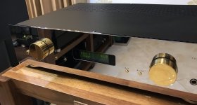
AVM Evolution M3 - Schematic now here - Circuit Description wanted
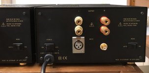
Images so as the owner's manual of this mono power amp are here:
AVM Evolution M3 Nachbau oder Original ?, Elektronik - HIFI-FORUM
http://www.avm-audio.com/fileadmin/pdf/German/Bedienungsanleitungen/Anleitung_Evolution_M3.pdf
short form data sheet is here:
AVM Evolution M3 - Manual - Mono Power Amplifier - HiFi Engine
Circuit description isn't online
Thank you very much.
For a good service maybe similar steps are to perform like at M1 and M2 - go to
Freie Ton- und Bildwerkstatt: AVM Monoblocke M1 Variante 2
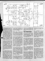
Diy Version of this mono amp:
stereoplay 1988 Monoblock from Günter Mania
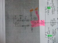
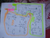
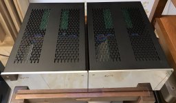
In the attachment the first series of images (last four are the scheatics of StBy control and protect circuit).
Images so as the owner's manual of this mono power amp are here:
AVM Evolution M3 Nachbau oder Original ?, Elektronik - HIFI-FORUM
http://www.avm-audio.com/fileadmin/pdf/German/Bedienungsanleitungen/Anleitung_Evolution_M3.pdf
short form data sheet is here:
AVM Evolution M3 - Manual - Mono Power Amplifier - HiFi Engine
Circuit description isn't online
Thank you very much.
For a good service maybe similar steps are to perform like at M1 and M2 - go to
Freie Ton- und Bildwerkstatt: AVM Monoblocke M1 Variante 2
Diy Version of this mono amp:
stereoplay 1988 Monoblock from Günter Mania
In the attachment the first series of images (last four are the scheatics of StBy control and protect circuit).
Last edited:
Here the attached files
Attachments
-
 AVM M3 Mainboard Solder Side.jpg1 MB · Views: 991
 -
 AVM M3 RN1 4x18K.jpg981.3 KB · Views: 839
 -
 AVM M3 RN2 4x18K.jpg979.1 KB · Views: 765
 -
 AVM M3 RN3 4x33K.jpg1,005.9 KB · Views: 726
 -
 AVM M3 Sticker-Left Ch.jpg980.6 KB · Views: 751
 -
 AVM M3 Sticker-Right Ch.jpg979.6 KB · Views: 703
 -
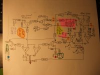 AVM M3E1 schema prot.jpg548.1 KB · Views: 908
 -
 AVM M3E1 schema prot-II.jpg625.2 KB · Views: 942
 -
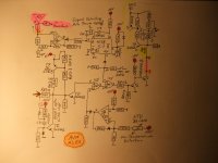
 AVM M3N1 schema stby.jpg766 KB · Views: 840
 -
 AVM M3N1 schema stby-II.jpg860.1 KB · Views: 865

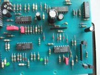
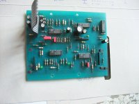
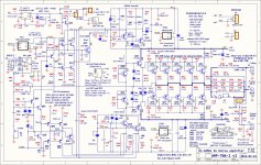
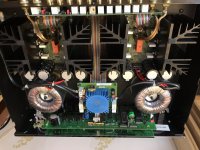
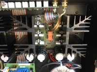
Identified serious Deficiencies so far
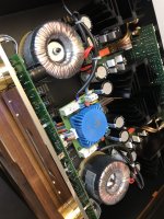
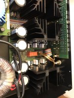
Due to thermal overload, I noticed at first attempt two major shortcomings straight away:
Too much power loss at three resistors:
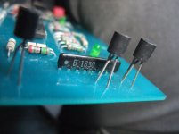
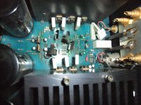
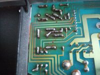
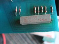
1) Between high voltage PS and input of 7815 and 1915 (basically 2 pcs. 680, in real live 20 pcs. with 68R at whole) - go to image No.6+7
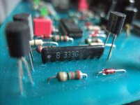
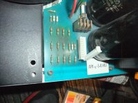
2) Between high voltage and relay for mains power On, 1x 680R 5W - go to attached mages No.8-10
Both I want to replace with versions in TO220 or TO247 outline like this under
https://www.vishay.com/docs/50051/lto100.pdf
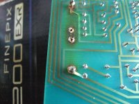
This is possible, because there is a sufficiently large metal surface, screwed and therefore thermally coupled with aluminum extruded rails between front and rear resp. back panel - go to the image No. 6.
Whether there is a better alternative here ?
Let's see what more shortcomings on closer inspection coming up.
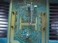
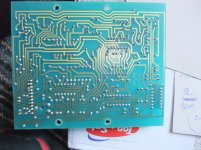
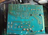
I'm afraid some more if you look at image No. 5, where is clearly to see the thermal stress nearly at the whole PCB area.
But one can now already say, that the purchase of used devices of this mono amplifier models is absolutely not recommended.
Due to thermal overload, I noticed at first attempt two major shortcomings straight away:
Too much power loss at three resistors:
1) Between high voltage PS and input of 7815 and 1915 (basically 2 pcs. 680, in real live 20 pcs. with 68R at whole) - go to image No.6+7
2) Between high voltage and relay for mains power On, 1x 680R 5W - go to attached mages No.8-10
Both I want to replace with versions in TO220 or TO247 outline like this under
https://www.vishay.com/docs/50051/lto100.pdf
This is possible, because there is a sufficiently large metal surface, screwed and therefore thermally coupled with aluminum extruded rails between front and rear resp. back panel - go to the image No. 6.
Whether there is a better alternative here ?
Let's see what more shortcomings on closer inspection coming up.
I'm afraid some more if you look at image No. 5, where is clearly to see the thermal stress nearly at the whole PCB area.
But one can now already say, that the purchase of used devices of this mono amplifier models is absolutely not recommended.
Attachments
-
 AVM M3E1 component side.jpg1,023 KB · Views: 426
 -
 AVM M3E1 component side-II.jpg988.2 KB · Views: 403
 -
 AVM M3E1 solder side.jpg1,017.7 KB · Views: 443
 -
 AVM M3G1 PCB component side-II.jpg1,020.7 KB · Views: 416
 -
 AVM M3G1 PCB solder side.jpg1 MB · Views: 424
 -
 AVM M3G1 Resistors between PS and input 7815+7915.jpg1,023.2 KB · Views: 401
 -
 AVM M3G1 Resistors between PS and input 7815+7915-II.jpg1,013.7 KB · Views: 387
 -
 AVM M3N1 680R for Rel1.jpg996.7 KB · Views: 370
 -
 AVM M3N1 680R for Rel1-II.jpg1,010 KB · Views: 370
 -
 AVM M3N1 solder side.jpg1 MB · Views: 394
Last edited:
What year have yours been built? In the AVM User Manual, the Date is 05/96, but on hifiengine.com it shows 2007-2009, so over 10 years later?
Quite a bit shocking, the lack of flwwless engineering, btw. I always thought that Mania knows what he is doing...
Thanks for sharing. The schematic looks very similar to the Stereoplay version, but with quite some important caps added....if built according to the first instructions/scematics, I believe these amps oscillated tremendously.
Thanks for sharing. The schematic looks very similar to the Stereoplay version, but with quite some important caps added....if built according to the first instructions/scematics, I believe these amps oscillated tremendously.
Last edited:
The homepage from 2006 shows the M2 (second version) - go toWhat year have yours been built? In the AVM User Manual, the Date is 05/96, but on hifiengine.com it shows 2007-2009, so over 10 years later?
AVM - AVM evolution M 2
and on the homepage from 2007/2008 was mentioned the M3NG with adjustable THD for tube amp character - go to
AVM Next Generation Audio Technologies GmbH
and
https://web.archive.org/web/2008122...in/pdf/English/Catalogue/avm_prog_en_0809.pdf
1996 was only the first version available, so I think.
check out the owner's manuals for M1, M2, M3 and M3NG under
Downloads - AVM AUDIO
Ah OK, so there is a M3 from 1996 onwards (the M1 being the first Power Amp, from 1988 or so) and a M3 NG from 2006 onwards.
Well my question was mainly - what version are you showing then?
M3 or M3 Next Generation?
Well my question was mainly - what version are you showing then?
M3 or M3 Next Generation?
I don't know.Ah OK, so there is a M3 from 1996 onwards (the M1 being the first Power Amp, from 1988 or so) and a M3 NG from 2006 onwards.
Well my question was mainly - what version are you showing then?
M3 or M3 Next Generation?
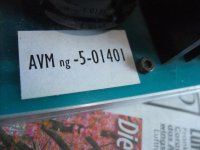
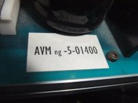
According the internal stickers with serial No "Next Generation" (M3NG) (go to the attached images)
OTOH - there are no THD adjustment present - that means "M3" without "NG".
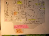
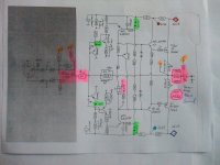
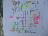
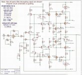
some update - power amp section now with the measured voltages and currents so as the protect function areas at whole for better understanding the theory of operation.
Follow questions rises up:
1) what is the benefit to switch on the zobel- (boucherot-) network with Rly-x togetherm with the LS relay (loudspeaker relay) ?
2) why is located the zobel- (boucherot-) network in front of the output buffer ?
3) what is the advantage resp. benefit to conduct the current of the coil from LS relay over the BE route from T3 instead direct to GND ?
4) there are advantages to the arrangement of the main power switch (for me it isn't a good choice, because the current surge while "swtich ON" is very large cause the electrolytics which are to be charged) ?
Because this monaural power blocks even in German are very rare, I have no hope of responding here
Attachments
Last edited:
check out this URLs:Do you know where the original drawings of these two circuit diagrams come from?
Winfield Hill's AMP-70 project
https://linearaudio.nl/winfield-hills-100w-10mhz-1000vus-amp-70https://www.diyaudio.com/community/threads/winfields-100w-dc-10mhz-1000v-us-amplifier.287023/
Thanks for sharing AVM
Attachments
-
 AVM besch3 im9.jpg225.9 KB · Views: 561
 -
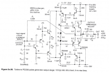 PG508.PNG120.6 KB · Views: 553
 -
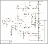 Amp-70 redraw input driver.jpg303.7 KB · Views: 621
 -
 AMP-70-2_v3 cct_0.jpg524.8 KB · Views: 758
 -
 2 德国AVM A2 合并功放机.jpg249.1 KB · Views: 502
 -
 9 AVM M4.jpg213.7 KB · Views: 325
 -
 10 AVM M4.jpg502.9 KB · Views: 353
 -
 7 德国AVM A2 合并功放机.jpg504.7 KB · Views: 942
 -
 8 德国AVM A2 合并功放机.jpg389.4 KB · Views: 356
 -
 10 德国AVM A2 合并功放机.jpg484.5 KB · Views: 375
 -
 12 德国AVM A2 合并功放机.jpg426 KB · Views: 520
Let me jump here with a little story of my Evolution M4.
Pair is almost 20 years old, 80% of that time in standby mode.
Looks like M4 (class A) unit is sharing pcb with M3 (class AB?).


I am facing the same story with overheated area of two sets of eight 68R resistors. Poor design, disappointing.


Also, the same issue with 680R on the power supply pcb (the one on the top on left hand side).

I have replaced this resistor with 8 Watt one.
On the amp boards, all 68R were removed and replaced with ~530R 10 Watt.
PCB is damaged near the overheated resistors.
I’ve measured main capacitors - each close to 16500uF (marked 22000) so quite well after all these years.
Control board:

Pair is almost 20 years old, 80% of that time in standby mode.
Looks like M4 (class A) unit is sharing pcb with M3 (class AB?).
I am facing the same story with overheated area of two sets of eight 68R resistors. Poor design, disappointing.
Also, the same issue with 680R on the power supply pcb (the one on the top on left hand side).
I have replaced this resistor with 8 Watt one.
On the amp boards, all 68R were removed and replaced with ~530R 10 Watt.
PCB is damaged near the overheated resistors.
I’ve measured main capacitors - each close to 16500uF (marked 22000) so quite well after all these years.
Control board:
I am repairing a M4 at the moment which did was not coming out of the standby mode (neitehr in "Auto" nor in "on" position).
The reason was a broken "on/off" switch (this switch is actually switching the +-65V supply after the recifier as shown above, thx for the schematics btw) which did not close. I replaced it and it is working or. Also the "auto/on" showed significant resistance when on, so I replaced it although it was still working.
My unit also shows the burned 68R resistors and PCB. It looks horrible but was still working. I tried to replace them but then the PCB tracks came loose, so I will now fit in a 680R 10W power resistor.
Apart from these obvious shortcomings I think it is a good amp. Only quality parts used, 2nd transformer for output stage. I bought mine used in the late 90ies and sold it over 10 years ago to a friend who now had the issues. Although the thermal design is not good it did last more than 25years and the thermal problems are easy to fix.
Power consumption for reference:
off: 3W
stand-by: 20W
on: 120W
I can post some pictures later, I have a different revision, probably older than the ones shown here.
- Home
- Amplifiers
- Solid State
- AVM Evolution M3 - Schematic wanted