Set the bias pots fully counter-clockwise. Does that eliminate the heating of the output transistors?
The 220 ohm resistors will likely cause the power supply FETs to overheat. Use the 75 ohm if the choice is 75 or 220.
The 220 ohm resistors will likely cause the power supply FETs to overheat. Use the 75 ohm if the choice is 75 or 220.
No, it doesn't eliminate the heating. If I connect rca and try to get music, I have no audio in output, but only noise.
What voltage I should read on tip35c/tip36c legs when they're connected?
What voltage I should read on tip35c/tip36c legs when they're connected?
Disconnect the RCA cables from the amp and measure the resistance from the RCA shields to the speaker wires that are NOT used when the amp is connected in bridged configuration. You should read 0 ohms. Is that what you read?
What is the DC voltage measured directly across the speaker wires for each channel?
How much current does the amp draw when the output transistors are heating up?
What is the DC voltage measured directly across the speaker wires for each channel?
How much current does the amp draw when the output transistors are heating up?
I read open circuit. So, quattro can be the probblem?
Across each speaker wire I read 1,5 volt DC.
I don't know how much current the amp draws, but I'm using 2,5ampere 12.5 volt transformer. I think it's drawing 2,5amp, because the green amp led without tip 35/36 do more light
Thank you so much Perry! You're fantastic!
Across each speaker wire I read 1,5 volt DC.
I don't know how much current the amp draws, but I'm using 2,5ampere 12.5 volt transformer. I think it's drawing 2,5amp, because the green amp led without tip 35/36 do more light
Thank you so much Perry! You're fantastic!
Last edited:
The trace in these amps sometimes burns near the RCA jacks. If there is no open trace, check the RCA ground connection to see if it's broken where it goes into the board.
There Was an open trace!!! Now I have no DC voltage in speakers outputs and no excessive current drawing. 🙂
Now, what I have to do?
Now, what I have to do?
Works cert good! Clean audio! Thank you very much! I mount all the transistor and after we can do bias regulation 🙂
If you don't have an amp meter on your power supply, you'll need to adjust the bias by the voltage across the emitter resistors. Set the bias so that you read 0.001v DC across the resistors (no input signal and no speakers connected).
Yesterday I tried to connect it in my car for any test. 2 minutes running at low volume and it comes in protection. Now I see no rail voltage: 11 irfz44 measure low resistance from gate to drain or source. What is the cause? Can be that I haven't installed Q201?
Now, what transistor I buy?
Now, what transistor I buy?
What size fuse dis you have inline with the amp when you installed it in the vehicle?
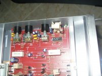
What is the purpose of Q201? If you don't know, post a photo of the area around it.
What is the purpose of Q201? If you don't know, post a photo of the area around it.
80 amp fuse
The amp had 2 problems: when I shut down amplifier, I eared a"bump" and after woofer oscillates a bit; when I connected left rca, with no music I ear periodic "tic" from woofer.
I thinked they couldn't cause problems, so I connected amplifier in my car, but running only left channel, because for the right channel I miss Q201. You can see it in my first post photo. Left channel has it (Q101) and it's a 2N5458, jfet...
If you want new photo I'll post it. Thank you!
Sorry. I didn't view the image full size. It's a muting transistor and should have no effect other than not doing it's job of preventing a turn on/off pop.
When testing any amp, you should use a relatively small fuse to help protect the amp in case there is a problem. A 20 amp fuse would have been enough to test initially.
When testing any amp, you should use a relatively small fuse to help protect the amp in case there is a problem. A 20 amp fuse would have been enough to test initially.
A 20 amp fuse in the vehicle would likely have protected the Z44s.
What happened to Z44 #12? Did it survive? If so, that could mean that it had a bad connection on it's gate terminal which could have caused the others to fail.
Also, this amp and a lot of the early Autotek (and similar amps) have weak drive circuits. The drive circuit may not be driving the FETs correctly. This likely has a regulated power supply so you need to lower the voltage of the 12v power supply to force the pulse width to go as wide as possible. If the current increases when the supply voltage is reduced, the FETs are not likely being driven properly. It shouldn't be a problem with the Z44s but if it is, you'll need to modify the circuit to make it reliable.
I'm assuming that none of the output transistors or the rectifiers are shorted, causing an overload of the supply.
I think it's good, because I read higher resistence from gate to drain or source, but I don't know if it works good.
I'll verify if tl494 produces correct output.
Rectifiers and output transistors are all good 😉
Lower gate resistences can't be the cause? They don't modify gate to source voltage? Can I have suggestions (websites, topics) to make PWM circuit stable and working well for irfz44?
I'll verify if tl494 produces correct output.
Rectifiers and output transistors are all good 😉
Lower gate resistences can't be the cause? They don't modify gate to source voltage? Can I have suggestions (websites, topics) to make PWM circuit stable and working well for irfz44?
Last edited:
If it reads more than 2x the gate resistor value, there is a broken connection somewhere.
The 494 is going to produce the correct output. The problem with the drive circuit will be beyond the output of the 494.
The lower gate resistors (compared to the originals) is necessary. It doesn't necessarily change the drive voltage. The drive voltage is essentially determined by the voltage on pins 8,11 and 12 of the 494.
Ok, thank you 😉 Maybe the problem can be fet or pin 8,11,12 bad connection. Now I order new irfz44. Where I can order and receive them in 48 hours?
I think the delivery time will be determined (largely) on the shipping method you're willing to pay for.
Try Farnell.
A bad connection on pins 8, 11 or 12 wouldn't be likely and wouldn't likely cause all FETs to fail.
Try Farnell.
A bad connection on pins 8, 11 or 12 wouldn't be likely and wouldn't likely cause all FETs to fail.
I found bad connections.
Yesterday with only 2x irfz44 installed, I connected ampli in my car (this time with 20 amp fuse), only one channel. Sounds very very well, it produces a lot of power! After I tried it @ 2 ohm (2x Ciare CM200) with 25 amp fuse: more power, high quality! Fantastic!
Now can you help me with other problems?
1- When I turn off ampli, I still hear "bump" (only left channel connected, it has jfet installed).
2- Gain doesn't work
3- Treble and bass have never worked
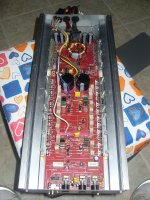
Here's an old pic of the parts interested.
Yesterday with only 2x irfz44 installed, I connected ampli in my car (this time with 20 amp fuse), only one channel. Sounds very very well, it produces a lot of power! After I tried it @ 2 ohm (2x Ciare CM200) with 25 amp fuse: more power, high quality! Fantastic!
Now can you help me with other problems?
1- When I turn off ampli, I still hear "bump" (only left channel connected, it has jfet installed).
2- Gain doesn't work
3- Treble and bass have never worked
Here's an old pic of the parts interested.
Attachments
- Status
- Not open for further replies.
- Home
- General Interest
- Car Audio
- Autotek 7600 bts problems