Hello,
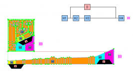
Many colleagues here in the forum already use CAD software to draw your Loundspeaker projects, some also use it to support their analysis in order to get input data to hornresp, and other prefer to uses the Microsoft Spreadsheets created by Brian Steele, for sure there are other options out there, but except the Spreadsheets that is freely available, probably all the other the users didn't share their tools and even if they share the major part probably is using payed software witch can reduce the accessibility. In this contex,t I decide to move from Solidword to FreeCAD and to share with you the CAD files containing Loundspeaker 3D model, fully integrated with parametric sketch which include and embedded Spreadsheet that you can be used as inputdata for Hornresp simulation and if you want/need further automation, you can use the macro to export Hornresp *.TXT inputdata.
Attached you can find a presentation about how to use it. The idea was to make it simple to use and freely available to everyone.
It would be very welcome and appreciated if you guys could test this tool and and provide feedback to improve it.
If anyone like the tool and want to make it available trough any wibesite. please do it, currently there is two models available, but it would be very fast to generate all Spreeadsheet models. Tapered fold are the most time consuming ones due to related constrains.
Check FreeCAD in the link below, available for Linux / Windows / Mac.
https://www.freecadweb.org
Attachments


Hi I downloaded the files and Think I have a bit of a learning curve to climb but like the unfolded sketches.
 In my own Solidworks sketches I added a secondary unfold sketch to give a way to approximate the hornresp input parameters when the direct unfold shape is not a good fit.
I have an error on the Paraflex type C spreadsheet.
21:09:23 <Spreadsheet> Cell.cpp(646): Paraflex_Type_C#Spreadsheet.F7: Property 'C03' not found in 'C03'
21:09:23 <Spreadsheet> Sheet.cpp(1493): Failed to restore Paraflex_Type_C#Spreadsheet: One or more cells failed contains errors.
Regards Xoc1
I have an error on the Paraflex type C spreadsheet.
21:09:23 <Spreadsheet> Cell.cpp(646): Paraflex_Type_C#Spreadsheet.F7: Property 'C03' not found in 'C03'
21:09:23 <Spreadsheet> Sheet.cpp(1493): Failed to restore Paraflex_Type_C#Spreadsheet: One or more cells failed contains errors.
Regards Xoc1
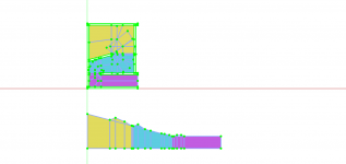
Here is an example of a Tham 10 with a secondary sketch that tries to take account of the irregular shape before the driver exit at S4

Edit I just noted that the dimensions have not updated to the red sketch- but hopefully you still get the idea!
Edit I just noted that the dimensions have not updated to the red sketch- but hopefully you still get the idea!
In my own Solidworks sketches I added a secondary unfold sketch to give a way to approximate the hornresp input parameters when the direct unfold shape is not a good fit.
In the sketch I made, you can also delete the secondary one and it will work, I was able to guarantee the horn progressions with constrains, and tapered horn requires a lot more constrains then straight one in the folding sections, so TH is little heavier to solve (update view) compared to Paraflex when you change sketches dimensions. You don't need to check the secondary sketch to fix the main one manually in this case. You have just a few inputs, all the rest are constrained by the Loundspeaker type you choose.
The difference for your picture is that in your secondary sketch the horizontal line is the dash doted one in the center, while both reds are tapered.
The one I build I considered one side always horizontal and the other tapered, the area progression is the same but the visual are different.
It can be easily changed if people prefer symmetric view. But if you check the TH horn for instance and the real enclosure, the H3 and H4 segments, you will see that one side of the horn is always horizontal.
I have an error on the Paraflex type C spreadsheet.
Yes, I wasn't able to fix it, but if you press F5 in the spreadsheet it fix the issue itself, so looks more like a bug.
Did you were able to export the Hornresp TXT data using macro? it was easy?
Thank you for the feedback.
New, ROAR model available.
The model is very close to the one proposed by the ROAR developer, but there are some very small differences in the length for some segments, and it's very strange how the H3 element is defined, looks liek the volume he simulates is bigger them the enclosure. Maybe he just approximate the model from the reality as much as possible once there is no specific model for ROAR in Hornresp. It might worth asking David.
Below the reference data and attached the files ziped.
https://www.martinsson.cc/blog/index.php?m=03&y=17&entry=entry170302-172317
Attachments

Thank you for all this effort. I tried FreeCAD, but was not very successful in learning it, so I use Fusion360. This will encourage me to look into it again. Do I understand it correctly, that you will parametrize the model to get all the necessary board dimensions and then can simulate directly in Hornresp? That is BoxPlan XLS sheets on steroids! Very cool!
@Brian Steele make a very good job with the Boxplan and I'd like to partnership with him, he already has a website and he knows very well a lot of different models, he could lead all developments, the difference is that I could contribute implementing for him with more modern tools not needing such a complex macro programming in excel. Microsoft exel is also a not viable option for many like once I use linux, so FreeCAD is cross platform and free like Hornresp is. Everybody won.That is BoxPlan XLS sheets on steroids! Very cool!
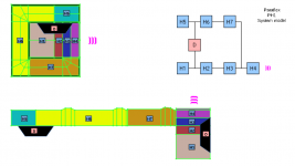
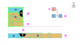
New, Tapped Horn - THAM
The THAM was defined to be able to use two different flare, a common flare for H1 and H2 and a second flare for H3 and H4, if you want, you can set the same value for both flares in order to have a single flare version.
Note: There might be some small differences for all models regarding the advanced center line from what concern witch face I pick up as orthogonal, but it don't affect the results, I can fine tune if needed.
@Xoc1 , you might wanna compare this model with the one you have.
Attachments
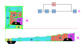

Hello,
Attached you can find the MLTL model updated in order to correct advanced center-line for better simulation accuracy. The secondary sketch was changed to be symmetrical and some other minor changes like little more freedom to change driver placement if needed without breaking the model.
Besides other loudspeakers models are already available, I'm working on related website to make it easy for people the get all the models they need and also to proper control the improvements or corrections through versions released for CAD and Macro, now they have a version release indication inside them.
When the website is officially release I'm going to create a different thread in order to better support and further discussions once this one was more focused to find volunteers to test and to collect initial feedback.
Attachments

Hello,
Just making you aware that the test phase ended and the project was officially released in another thread, see the link below.
If you downloaded any model from here, they are outdated and worth getting a new one from the website with all found issues fixed, at least I hope so.
Thanks @pelanj and @Xoc1 to folow this thread.
https://www.diyaudio.com/community/...plan-hornresp-integrated.391237/#post-7147619
- Home
- Loudspeakers
- Subwoofers
- Automation / Integration between Parametric CAD and Hornresp - Volunteers request.