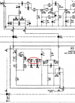
I have a theoretical question concerning below extract of the Marconi TF-2015 (10MHz-520MHz AM/FM signal generator):
What I don't understand is the function of the 2 Schottky diodes inside the red circle.
In addition, why each Schottky diode has in addition an additional 100pF parallel capacitor, while the Schottky's are exactly having a minimal 2 pF junction capacity, just to be able to perform very fast switching (low "charge buckets").
So the lower half of the circuit is from A17, the Automatic Level Control, controlling the current through the active (selected) oscillator circuit on A12.
At the top left, the carrier is fed from the selected oscillator circuit on A12 into the RF output amplifier circuit A17.
(all the remainder of the RF-amplifier, further to the right, with the BFR90 transistors, is pre-amplifying stage of the RF-amplifier, which we are no further considering at this point.)
Now, if the amplitude of the oscillator signal (taken from a Philips PM5145/01 12MHz generator) is increased, then I observe the following :
1) the DC voltages as measured at both the red arrows, start deviating more and more from each other.
2) the amplitude of the AC-components at both points start increasing also.
At this time, it is noticed that the amplitude at the cathode of D1 is increasing stronger than the amplitude at the anode of D2, which is connected to ground via C3.
So far I am still following with everything.
But now: what I do not understand is the exact function of those 2 series-Schottky's in de base circuit of the left-hand balancetransistor TR1 at the bottom.
And with each Schottky diode in addition being bridged/shunted by a ceramic 100pF.
Can anyone tell me about the exact purpose of those circled Schottky's ?
Why two in series ?
Why these 100pF capacitors across ?
Many thanks!
PS: the full "Instruction Manual" for the Marconi TF 2015A can be downloaded from the web. But if desired, I can always mail it. It's a 5645 KB pdf file.
An externally hosted image should be here but it was not working when we last tested it.
What I don't understand is the function of the 2 Schottky diodes inside the red circle.
In addition, why each Schottky diode has in addition an additional 100pF parallel capacitor, while the Schottky's are exactly having a minimal 2 pF junction capacity, just to be able to perform very fast switching (low "charge buckets").
So the lower half of the circuit is from A17, the Automatic Level Control, controlling the current through the active (selected) oscillator circuit on A12.
At the top left, the carrier is fed from the selected oscillator circuit on A12 into the RF output amplifier circuit A17.
(all the remainder of the RF-amplifier, further to the right, with the BFR90 transistors, is pre-amplifying stage of the RF-amplifier, which we are no further considering at this point.)
Now, if the amplitude of the oscillator signal (taken from a Philips PM5145/01 12MHz generator) is increased, then I observe the following :
1) the DC voltages as measured at both the red arrows, start deviating more and more from each other.
2) the amplitude of the AC-components at both points start increasing also.
At this time, it is noticed that the amplitude at the cathode of D1 is increasing stronger than the amplitude at the anode of D2, which is connected to ground via C3.
So far I am still following with everything.
But now: what I do not understand is the exact function of those 2 series-Schottky's in de base circuit of the left-hand balancetransistor TR1 at the bottom.
And with each Schottky diode in addition being bridged/shunted by a ceramic 100pF.
Can anyone tell me about the exact purpose of those circled Schottky's ?
Why two in series ?
Why these 100pF capacitors across ?
Many thanks!
PS: the full "Instruction Manual" for the Marconi TF 2015A can be downloaded from the web. But if desired, I can always mail it. It's a 5645 KB pdf file.