Hey guys, noob alert!
I've bought a cheap used TEAC SW-P200 subwoofer and it works just fine for my use case... apart from the damned auto standby feature!
There's no way to turn it off or change the sensitivity of it so I'm stuck with the sub working great while there's enough "oomph" in the signal (like listening to music or action scenes/games) but as soon as the content gets quiet it turns off after about a minute.
It turns back on as soon as "something" happens, like an explosion, but its annoying and the poor relay switch has to continuously tick-tack every few minutes...
Unfortunately there's no way for me to increase the signal level at the source so probably the easiest way would be to just remove the relay and bridge the contacts but if possible I'd prefer to keep it as is and make it more "sensitive" to the incoming signal or increase the shutoff time
I cant find any service manuals or schemes online for this model and honestly even if I did I still wouldn't understand what I'm looking at without some help 😆 I've opened the back and there are 2 PCBs connected by a flat cable, the main one where all the main electronics live and a smaller one where the LFE IN and volume knob are connected.
What do you think? Is it possible just by looking at some photos for you guys to figure out how the standby circuit works and help me find what can be replaced? Hopefully a resistor or something like that!
Thanks a lot!
I'm back with some pictures and findings... probably 🤣
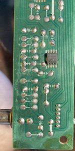
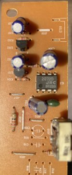
The sub has 2 boards, the main one and the input one.
On the input board there are 2 chips, the first is a NJM2068 amplifier - I've attached the spec sheet

The 2nd one is a "SIGNAL LEVEL SENSOR SYSTEM" chip... something tells me it's the one I'm looking for 😅 I've attached the spec sheet

I dont have fancy equipment, just a multimeter and I've been following the circuit w/o power and signal so I cant be too sure of what I've found out...
I dont understand what the hell is going on around the amp chip but what Im sure of is that the A output of the chip goes pretty much directly to pin 1 of the signal level chip (I have continuity using the multimeter)
On the signal chip pin 6 (OUT1) goes (after some more mystery components 😀) to the ribbon cable that connect to the main board (probably to the relay switch)
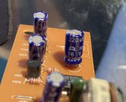
I dont really understand if anything can be done to increase the signal level but Im more confident about increasing the shutoff timer. Pin 5 is called "Capacitor for Recovery time" and it's currently a 220uf 16V cap:

If I'm not mistaken this should tell the chip after how long to cut the OUT1 signal to the relay to cut power, right?
The timer is about 1-2 minutes at the moment, do you think I can increase that by replacing the cap? I'd like to reach 5-10 minutes if possible!
Can you help me figure out the value I should replace it with?
Thanks!
The sub has 2 boards, the main one and the input one.
On the input board there are 2 chips, the first is a NJM2068 amplifier - I've attached the spec sheet

The 2nd one is a "SIGNAL LEVEL SENSOR SYSTEM" chip... something tells me it's the one I'm looking for 😅 I've attached the spec sheet

I dont have fancy equipment, just a multimeter and I've been following the circuit w/o power and signal so I cant be too sure of what I've found out...
I dont understand what the hell is going on around the amp chip but what Im sure of is that the A output of the chip goes pretty much directly to pin 1 of the signal level chip (I have continuity using the multimeter)
On the signal chip pin 6 (OUT1) goes (after some more mystery components 😀) to the ribbon cable that connect to the main board (probably to the relay switch)
I dont really understand if anything can be done to increase the signal level but Im more confident about increasing the shutoff timer. Pin 5 is called "Capacitor for Recovery time" and it's currently a 220uf 16V cap:

If I'm not mistaken this should tell the chip after how long to cut the OUT1 signal to the relay to cut power, right?
The timer is about 1-2 minutes at the moment, do you think I can increase that by replacing the cap? I'd like to reach 5-10 minutes if possible!
Can you help me figure out the value I should replace it with?
Thanks!
Attachments
Yes you are correct about the function of that capacitor, I've seen some circuit use 1000uF for longer delay off time.If I'm not mistaken this should tell the chip after how long to cut the OUT1 signal to the relay to cut power, right?
The timer is about 1-2 minutes at the moment, do you think I can increase that by replacing the cap? I'd like to reach 5-10 minutes if possible!
My suggestion is to solder a 680 or 820uF capacitor on the PCB trace side, in parallel with the 220uf capacitor, to increase the capacitance value, please make sure the capacitor is installed with the correct polarity.
Thanks a lot for the reply! What if I use a single 1500uf? Is it still better to keep the old one in parallel?
Thanks!
Thanks!
- Home
- Loudspeakers
- Subwoofers
- Auto standby feature, looking for a way to increase shutoff time or sensitivity to signal