Recently I rebuild a pair of Audiostatics ESH100. An almost full range electrostatic with integrated bass reflex for the lowest octave.
Listening to the end result I noticed that one of the ESL's had a lower output and that when playing louder distortion is occurring sooner than on the other one.
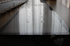
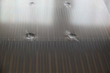
To stabilize the diaphragm Audiostatics applied silicon dots between the wire stator and the diaphragm. Upon inspection it turned out that on the low output speaker the silicone dots were much bigger than on the other one. And what's more it looks like the dots are sucking the diaphragm closer to one side of the stator. The pictures are showing clearly that the silicon sealant is producing dents in the diaphragm. In my opinion caused by shrinking of the sealant.
I would appreciate to get some help about alternatives, like advice about non shrinking (clear) silicon kit or paste, the use of double sided foam tape or perhaps the use of kneadable rubber/putty.
Listening to the end result I noticed that one of the ESL's had a lower output and that when playing louder distortion is occurring sooner than on the other one.
To stabilize the diaphragm Audiostatics applied silicon dots between the wire stator and the diaphragm. Upon inspection it turned out that on the low output speaker the silicone dots were much bigger than on the other one. And what's more it looks like the dots are sucking the diaphragm closer to one side of the stator. The pictures are showing clearly that the silicon sealant is producing dents in the diaphragm. In my opinion caused by shrinking of the sealant.
I would appreciate to get some help about alternatives, like advice about non shrinking (clear) silicon kit or paste, the use of double sided foam tape or perhaps the use of kneadable rubber/putty.
Attachments
The diaphragm distortion in your pictures looks relatively small and localized. It seems like a low percentage of diaphragm area and a low percentage of spacing, so I would expect the impact to be minimal.
From the reflections, it looks like the diaphragm is mostly flat. Is there something that's not showing up in the picture? Would a straightedge place on the diaphragm show it better? Can you estimate the offset as a percentage of diaphragm-to-stator spacing? And estimate the percentage of diaphragm affected?
Unless there's something I'm not seeing, I wouldn't expect the problem you're describing from minor diaphragm issues.
Did you swap the electrostatic panels between the interfaces to make sure something else isn't causing the problem? Have you confirmed that you are getting full bias voltage on your diaphragms (or if you can't measure voltages that high, that diaphragm resistance is consistent and has a good connection)?
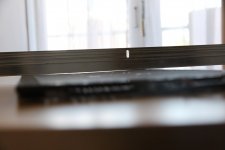
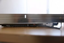
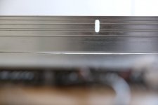
mattstat, I added some pictures to give you a better idea of the rate of deflection of the diaphragm. In the middle of the diaphragm there is a dent of about 0,5 mm. This is from top to bottom and not only in the vicinity of the silicon kit. The stator to diaphragm distance is about 3,5 mm. I think the deflection is caused by the sucking force of the kit. I have no idea if this deflection is contributing to distortion and lower output of this speaker. (see pictures)
I have to confess I didn't check the consistence of the diaphragm coating. The connection of the diaphragm to the bias circuit seems correct to me. A copper charge ring all around. Very fast charging after powering up and a (non standard Audiostatic) blinker circuit that is firing at a normal blink rate.
In the mean time I think it would be useful to get myself a high voltage probe to check the bias voltage. There are several build instructions for hv probes on the net. As the energy in the bias network of an esl is limited I think a diy solution is okay.
Attachments
Thanks for the extra pictures. They really help show the diaphragm displacement.
Without the speakers in front of me I'm guessing a bit, but even that amount of displacement doesn't seem like it should cause major problems as long as everything else is right. The panel resonance may have shifted some, which can change the sound, but that doesn't explain noticeably different distortion or sensitivity. If you have an old analog signal generator, you can sweep through the bass range with a sine wave and identify the resonances to see if there are major differences between the panels. It will also highlight tendencies for the diaphragm to rattle. You don't need much voltage to do this. A few volts RMS from the amplifier is usually sufficient.
From a hardware standpoint, voltage handling for the resistors is the main thing to watch for on your DIY probe. If you are following someone else's design you should be OK on that. Safety can be an issue as well. If you're measuring after a current limiting resistor, there's little energy/threat. If you're measuring the voltage multiplier directly, currents are higher, especially in circuits connected to mains voltage. Most designs address packaging the probe to minimize hazards, so as long as you're careful a DIY probe can be an acceptable solution.
Last edited:
Mattstat thank you for your worthwhile input.
Tried to check the consistency of the diaphragm coating. Two coins on the foil and measuring with my dmm. Resistance infinite. Alas meter has max reading of 40Mohms. Found trick to sort of overcome the limitations of my meter by using a known voltage source. So two things to think about, measuring bias and coating resistance.
By the way when I think back of the listening test where I turned up the volume more and more this esl not only distorted but also produced a few tick or click sounds. Arcing perhaps? However the diaphragm is completely free of (visible) burn holes. Could there be a relationship with the reduced diaphragm to stator distance. Close to the dents the displacement is almost 1 mm.
I have an older Beckman/Wavetek DM15XL that has a 2000 megohm range. You can find them used periodically, and they weren't expensive to begin with. For typical diaphragm coatings, it's sufficient. There are now reasonably priced surface resistance meters on the market that can read very high resistances, but I don't have any experience with them. I've seen them mentioned in other threads though.
One of my concerns was that your diaphragm coating resistance may have been too low, but resistance being over range on your meter likely takes care of that worry. That was still a useful test.
You won't normally see any diaphragm or coating holes from brief overdriving or minor arcing. It typically takes a while or an extreme event to do that kind of damage.
If your stator insulation is intact, you won't typically get a significant arc either, so won't do any damage even if there's periodic popping/ticking/crackling. During an overvoltage event, most of the voltage is dissipated through the insulation instead of in the gap, so arcing isn't as much of an issue in a proper insulated design. They still have limitations on total voltage across their gaps though, so overdriving them will lead to distortion or popping/ticking.
If you suspect that your insulation has issues, one thing you can do is play at high levels in the dark and carefully inspect the ESL panel for any signs of corona or arcing.
Under dynamic conditions at moderate drive levels, the areas close to the dents will likely be of limited concern because diaphragm motion will be limited by the physical connection to the dots and you probably won't be near air's breakdown limits even at the locally reduced spacing.
If you have ticking/popping with no music playing, I would lean toward the reduced spacing in those areas not being able to handle the full bias voltage.
If the ticking/popping you described is happening at very high drive levels, the areas of reduced spacing could be the limiting factor for ultimate output as it is since 1 mm is a more significant portion of the intended spacing, and something has to give eventually if you're pushing up to the limits of the panel.
Last edited:
I used the Htec coating of forum member Martin Jan Dijkstra. He is specifying his coating as having a resistance of between 10^8 and 10^9 ohms. I applied a very thin layer so I wouldn't expect the resistance being too low. It's nice to have it confirmed.
It's still possible that the bias of both speakers is at differing levels. That's a job for my diy hv probe.
Last but not least the displacement of the diaphragm. Your remarks and my OCD are telling me that a fresh foil is required. Because I think it's impossible to loosen the diaphragm from the dots and inject additional kit underneath. Remaining question is what about the dots ??? I'm reluctant to use (shrinking) silicon dots again.
If you get through the other tests without finding anything, I would also drive the "bad" panel from the other speaker's interface to make sure there is not a problem in the step-up transformers. If the problem follows the panel you are worried about, that's more indication that a new diaphragm may be required.
If you want to use tape instead of silicone for spacer dots, 3M VHB Tape 4941 might work. It is plasticizer resistant, so should stick OK to the stator insulation. 3 layers of it will get you to a little over 3.4 mm. The exposed adhesive between wires will probably collect dust, but I think that could be prevented a couple different ways. It is gray though, so may not be acceptable to you. I couldn't find a clear tape that looked suitable in a quick search. If your dots are small enough and only at the spars, neither of those may be a problem though.
There are low shrink silicones available for mold making, but I don't know if there are any high viscosity versions. It sounds like your other speaker turned out better with smaller dots. That might be an option also. You could run some quick tests of various dot sizes to see what is optimal for your technique and material.
mattstat thx again, I will do the tests as you suggested step by step. First I will try to get a HV probe to check if they are equally biased. I'm really lucky to also have a set of Quad ESL's because without music I'm lost.😉
To build a bias measurement probe with a 1:1000 factor is a 200Mohm high voltage resistor for the voltage divider high enough or would be better to go for a 1Gohm ?
1,000 megohms (1 gigaohm) is more common for high voltage probes, so your results will be more meaningful/comparable to others if you use that value. Also, even that input impedance can significantly load some multiplier-based circuits. It depends on frequency and where you are trying to measure. High frequency inverters typically handle additional loading better. Measuring before the current limiting resistor can also help.
Though part of the question is whether you are worried about absolute vs. relative measurements.
Though part of the question is whether you are worried about absolute vs. relative measurements.
Then I will go for the 1Gohm resistor. I think most interesting for me is the relative voltage. That is comparing left and right speaker.
Btw I have to confess that every time I’m impressed by the thoughtfulness of your answers. That makes me curious how you got involved in diy audio and especially the world of electrostatics. If it’s impolite to ask you this personal question I apologize.
Btw I have to confess that every time I’m impressed by the thoughtfulness of your answers. That makes me curious how you got involved in diy audio and especially the world of electrostatics. If it’s impolite to ask you this personal question I apologize.
Thank you for the kind words.
The short answer: I'm mostly self-taught with some help from more experienced friends.
The longer version is a meandering story, and I'm leaving out some people for brevity, but here goes.
My early audio exposure was through an older brother that was into stereos. He had typical mass market gear, but it got me involved when I was young. He bought a book on building typical box speakers at some point, which got me thinking along those lines. He also had a subscription to Audio magazine, and I remember their equipment directories that seemed to list everything that was available. Most of it was out of my reach, but seeing it gives you ideas. A high school physics teacher provided a little high-voltage electronics exposure, which came in handy also.
In my late teens we had two or three higher-end audio stores in town. One had friendlier employees, so I started spending time there. I got to know most of the staff and some car audio manufacturers’ representatives. When IASCA was getting popular, those contacts led to me being a sound quality judge at competitions. I got to hear a lot of different equipment integrated in different ways, which was useful. People generally respected my opinions on sound quality and system tuning, which was encouraging.
I think my first knowledge of electrostatics came from a conversation I had with a friend from the audio store. The technology sounded interesting and exotic, so I started looking into it. I believe Audiostatics were the first ones I saw in person, followed shortly thereafter by Martin Logans. In addition to the sound, I was drawn to their apparent simplicity and the idea that the drivers could be built without much specialized equipment. The cost in parts seemed low vs. their retail prices, so that was a motivator also.
I got a copy of Ron Wagner’s book Electrostatic Loudspeaker Design and Construction. In it, he referenced a specific transformer company's units for the audio step-up. I called them with some questions they could not answer, and they gave me Ron’s number. I sheepishly called him, assuming I would be bothering someone that had much better things to do with their time. Instead, he was patient, open, thoughtful, and encouraging. He freely shared his knowledge, time, and library of patents and papers. Finding that kind of information was much more tedious in those days, so his pointers saved me a lot of time and effort. He was a good guy.
Once I had a decent grasp of the basics and got through building some pretty bad first panels, I started working to improve what I made and understand more of the nuances. I have an optimizer’s mentality in many ways, and designing electrostatics certainly gives lots of opportunities for that. Over the years, I built most of the different panel configurations you could and refined my methods. I found various people, books, patents, and magazines helpful along the way.
Electrostatics do have their limitations though, so my more recent DIY pursuits have mostly been with dynamic speakers.
I worked a little here and there in audio, but figured out pretty early that it's a tough market that chews up many good brands and people. Most of my work history is in research and development, but not in audio.
That is an interesting story especially your contact with Ron Wagner. Nowadays you can find everything on the net but I guess your contact with Ron goes a long way back.
My hifi audio story started in my teens. I had no money at all but was always listening to music and tinkering with my old radio gear. I had an older brother like you who had much more money and decided to build his own speakers. Of course I was first in line to assist him. If I remember well it was a Peerless three way thing in a BR. When it was finished we thought it was the best thing since sliced bread.
Shortly thereafter I started to visit audio shows which in the hifi boom of the seventies and eighties became very popular. Listening and comparing we soon realized our professional looking cabinets were sounding like sh..t.
A few years later I started a study in economics and earned my first money. Now it was time to buy me some good audio stuff. After a lot of questioning, doubting and hesitating I bought my first serious set consisting of a German Dual record player, the famous Quad 33/303 amp and a set of B&W DM3 loudspeakers. Maaaaaan I was so happy.
The B&W's were in my eyes and ears a wonder of modern speaker technology and everyone who heard them was impressed. Alas, in that time I had never heard of listening fatigue. But when the time went by and the more I listened to my favorite music the more often I wanted to pull the plug. What in heavens name was happening here. In fact this was the start of an always ongoing hunt for a better reproduction in my home. After more visits to shows, listening and talking to people I decided to get rid of my B&W's. In my ears they were unlistenable.
As a frequent visitor of the Quad booth at audio fairs I always enjoyed the Quad ESL 57. In my eyes it was a monstrous thing with a wonderful and transparent sound image. My girl friend I was about to marry turned out to be very tolerant to ugly hifi gear. Price of the Quad ESL's was then relatively low when compared to the absurd prices nowadays. So one fine day there they were brought in. In my room they looked much larger than in the show booth. But boy o boy what a revelation they were and what's more I could listen to them for hours and hours without strain. And so I got hooked to electrostatics and although in the following years I switched a lot of my audio gear for something "better" the esl's were here to stay.
I always had a keen interest in the technical side of my audio gear but being not educated in electronics the finer details eluded me. A few years ago I retired and soon after I discovered this forum. And what a forum it is, a lot of really smart guys like you who were more than willing to help newbs like me. I started my first project with the build of an PA03 chipamp and reported my build in this forum. It was funny because I discovered that even a newb like me could help other people. In a dutch forum I stumbled upon a design of a composite chipamp which I also build. A complex design completely in smd technique. Followed by a relatively easy TPA3255 build.
Then "disaster" struck. One of my QUAD 2805 esl's which I bought secondhand produced a nasty distortion. I thought I've got nothing to loose so let's try to fix it myself with hopefully the help from the guys at diyaudio. And they did, in fact they guided me through the whole process. I was so thankful and at the same time proud as a peacock when after half a year of piecing together all the information, I got my ESL's fixed and back in the living.
Then I thought I've learned a lot about esl's why not try my fresh knowledge on another pair of electrostatics. So when I stumbled upon a pair of worn out Audiostatics which I could buy for a modest price I bought them. After a complete rebuild including fresh diaphragms, coating, HV wiring, fresh paint and so on they are sounding good (however I'm not fully convinced of the concept of this hybrid system) But as you know there is a level difference in left to right channel and that is where I am right now.
- Home
- Loudspeakers
- Planars & Exotics
- Audiostatic, dot problems