Hi.
I recently acquired an AudioSource Amp200 (circuit boards inside say "Amp200/300), and it plays fine for a while after power-up, but after 3-5 minutes, the right channel cuts out, followed by the left approximately 5 seconds later.
When I press the power (off) switch, there's a (very) brief burst of music, then it turns off.
As long as I wait at least 10-15 seconds before powering up again, the amp will play music, always followed within a couple minutes by the right channel muting, then the left (always 5 seconds later).
I haven't been able to find a schematic for the output section of this amp...
Anyone out there have a schematic to share?
Any ideas about what's going on and how to fix it?
Thanks for your kind assistance.
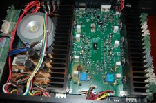
A picture of the uncovered amp is attached.
-Chas
I recently acquired an AudioSource Amp200 (circuit boards inside say "Amp200/300), and it plays fine for a while after power-up, but after 3-5 minutes, the right channel cuts out, followed by the left approximately 5 seconds later.
When I press the power (off) switch, there's a (very) brief burst of music, then it turns off.
As long as I wait at least 10-15 seconds before powering up again, the amp will play music, always followed within a couple minutes by the right channel muting, then the left (always 5 seconds later).
I haven't been able to find a schematic for the output section of this amp...
Anyone out there have a schematic to share?
Any ideas about what's going on and how to fix it?
Thanks for your kind assistance.
A picture of the uncovered amp is attached.
-Chas
Attachments
This generic design seems to be marketed through a variety of agencies like Ebay, Parts Connection and MCM. The brands vary so "Audiosource" is probably not the one to find schematics under. It is also marketed here in Oz under another brand again so it may prove elusive.
Otherwise, it's pretty clearly a thermal limiting issue if it takes 5 mins. to cut out - presumably with any or even no signal or output. Is that actually the case and what speakers/sound level are you using?
Otherwise, it's pretty clearly a thermal limiting issue if it takes 5 mins. to cut out - presumably with any or even no signal or output. Is that actually the case and what speakers/sound level are you using?
Otherwise, it's pretty clearly a thermal limiting issue if it takes 5 mins. to cut out - presumably with any or even no signal or output. Is that actually the case and what speakers/sound level are you using?
Yes, with or without a music signal present (I keep a DC voltmeter attached to te output to watch the DC offset, which is between 2-10mV), the amp cuts out within 5 minutes from "cold", and tried again soon after that, even less than one minute. The speakers are 8 ohm miniatures I always use for testing.
When tried without music signal, I do not hear any telltale "clicks" indicating that its not the protection relays that are muting the outputs... Then again there's that (very)brief burst of output (or 2-10mV DC offset) upon powering down the unit...
😕
resurrecting this thread again... I have a left channel that has gone silent, both A & B speakers. The right channel plays fine both A&B.
I have checked the normal culprits, I have solid AC coming in, good DC coming out of the PSU board (+/-50Vdc, 24 Vdc and +/-15Vdc) so I don't think anything is wrong with the transformer or PSU board.
I have also checked all the large resistors (ones marked "fuse" on attached schematic) and compared them to the good channel and they all seem to test similar. I have also tested the continuity with the RCA's and the input board and then to the amp board, just to make sure a wire hadn't come loose or broken. Those all check out good.
I have tested all the mosfets on the heat-sink, comparing the ohms and diode results with the good channel and they all match, so I don't think it is a blown mosfet on the heat-sink. I have not tested all the transistors on the board, though.
Any ideas? I would assume it is either the amp board has blown some transistors, or the input/output board(s) have a defective part hindering the left side from output of a signal to the speaker terminals.
Additionally, any idea what this attached pic is? I can't seem to locate what this HIGHLIGHTED part on the schematic is called, in case I need to replace it?
Also, any suggestions of a good place to get replacement transistors? A lot of talk on here about fakes. I don't want to go to the trouble of fixing it, only to use inferior parts and they don't last.
Attachments
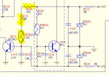
RTH101 and RTH102 look like some form of Thermistor.
NC may be not connected (i.e. omitted).
The 103 could be a resistance value, or a code
But Thermistors can be PTC or NTC. You need to check which.
NC may be not connected (i.e. omitted).
The 103 could be a resistance value, or a code
But Thermistors can be PTC or NTC. You need to check which.
Thanks for the reply AndrewT, yes that makes sense and after searching on Mouser, it appears to be a 10k NTC thermistor. I hope to do some further probing and testing tonight.
Found that resistor R121 appears to have been taken out and soldered to one leg of R141 and one leg of the RTH-102. Not sure why, but looks like same orientation as schematic, maybe they didn't want to pull the board out, so they soldered from top side.
Found that resistor R121 appears to have been taken out and soldered to one leg of R141 and one leg of the RTH-102. Not sure why, but looks like same orientation as schematic, maybe they didn't want to pull the board out, so they soldered from top side.
Compare output DC offset on both channels. Easy since the unit does not have any protection circuitry. Also means test speakers better be expendable and/or connected via a suitably big DIY bipolar capacitor (two polars of a few 1000 µF 50+ V back-to-back).
Make sure the output relay is making good contact. It's Chinese parts quality, right? That especially goes for intermittency issues.
Make sure the output relay is making good contact. It's Chinese parts quality, right? That especially goes for intermittency issues.
I just compared all channels DC offset, according to the step by step on Wiki.
Right Channel on A and B measured at 19-20 mV over a 20 minute test.
Left channel on A and B measured at 0-0.1 mV over a similar 20 minute test. Safe to say, nothing is happening on the left channel.
I re-tested (diode check and resistance) all the mosfets/transitors on the heat-sink again last night and found one (Q119) that measured significantly different than it's matching right channel part. Also fixed a couple odd resistor mis-placements and checked over the entire amp for any solder bridges.
I have ordered all 7 replacement mosfets from digikey ($14) and will replace them. I also bought parts to build a dim bulb tester. Don't want to blow up the new parts before I can check everything out.
Dim bulb tester is good. Also blocking cap on speakers.
You need to buy an analog VOM with 2 vac & 20 vac scales to trace music through the amp to see where it is dropping out. Or buy a scope. the ****ese ones,are probably same high quality as the amp. My used ones have been a waste of time & money. I use a simpson 260 XLPM analog meter, 35 years no ecaps to fail it that. You need a .047 uf to .47 uf cap in series with the negative lead to ground, to make sure DC doesn't move the pointer on AC scale. A $20 GB analog meter from the hardware store may do some good. DVM average over 4 seconds and mine all product random numbers on AC scale on music. (sears, harbor freight)
I exercise amp with a $2 radio, earphone jack. The earphone to RCA adapter cable was $6.. Don't use a cell phone, too expensive.
Vefore buying parts, check for music or absence in input area after pots or connectors or select switches, collector of first transistor, collector of 2nd transistor (VAS), if it is not before that You have to check current from driver stage to output gates. this is a two lead measurement across some resistor. Back to voltage to ground to check on input and output of speaker protection relay.
You test NTC, PTC resistors on ohms scale, the resistance should change when you hold them with fingers, or blow hair dryer on them.
I haven't blown any NTC yet. PCAT power supplies have a 10 k NTC resistor in them usually attached to the heat sink. Lots of free diodes & resistors, too. I sort them in baggies, by decades at first, now by individual values. There are no useful parts stores here, I usually can parallel some values to replace a blown resistor without an $8 shipping charge and 3-4 day wait.
A newish amp, poor solder joint quality can be what is stopping the music.
Sources of real transistors, newark (SC) mouser (TX) digikey (MN) Allied elec (?) Avnet direct. Read the specs, they sometimes sell rejects with a 1/200 nominal wattage or current rating, great price, useless part. Also read package code, there are substitutes with the same PN except suffix, and totally different package.
I test mosfets with ohmmeter. short g to s with clip lead, measure D to S resistance. Rds Sould be infinity forwards, can be one diode drop backwards due to flywheel diode.
Last edited:
Ok, figured out the Q109 was not testing as it should, ordered that and few other parts from digikey. Got the parts a few days ago and replaced the Q109 with a new transistor and all is working.
Question - I was running it at low volume with some cheap speakers to make sure it doesn't have any other issues and after about 30-45 minutes or play, I took all the transitors tempatures.
Q219 is running about 15-degrees F (8-10 degrees C) hotter than the same Q119/Q109, as well as the resistors and capacitors around that transistor. They are all running about 80F, compared to 65F for the same parts other channel.
Is this something to worry about? I made sure it is tight to the heatsink and appears to have suffcient thermal paste.
Make sure all of the output transistor emitter resistors are good, if one is open the hot transistor may be doing all of the work. Check Q209's emitter resistor. What is Q209's temp?
Craig
Craig
Make sure all of the output transistor emitter resistors are good, if one is open the hot transistor may be doing all of the work. Check Q209's emitter resistor. What is Q209's temp? Craig
Thanks for the reply---I ran the amp for 30-40 minutes to get it warmed up, temperature of Q209 is the same as all the other transistors, runs at 62-65F, as do all the resistors around Q209 and other transistors.
Only Q219 and its surrounding resistors are running 10-15F hotter than all the others on the board.
Powered the amp off and took measurements of all the resistors around Q209 and they measure the same as Q219/Q109 and Q119, so I don't think it is an open resistor causing an excessive load.
I am measuring in a cool basement environment (about 50F) so it takes hours of music to get it to full temperature. I might leave it on tomorrow and see what the maximum temperature I can get from all the transistors to compare.
Compare all of the output emitter resistor voltages, Q219's emitter voltage should be higher if it's running warmer than the others.
Craig
Craig
Last edited:
I just measured all the resistors while music was playing. They are within 0.2vDC of each other. So nothing is obviously way over-heating or over-voltage that I can find? Just hotter than the others. But it's weird so I'd like to find the cause.
Paul
Paul
When the idle current is adjusted for tens of millivolts I would say .2 or 200mv is quite a difference. Measure them with no signal no load.
Craig
Craig
At idle I measured all the resistors except the 5w 0.01r resistor (can't get to bottom of board right now). And they all measure at spec and drawing same current (very little). After 1 hour of a 30 Hz sine wave Q219 still measures about 6-8F degrees warmer but still at 80F and the heat sink is cold (65F).
Noob question but where is the emitter resistor? I'm pretty sure it's the 5W0.01r I can't get to but can someone confirm and I will take the board back out tonight possibly.
Paul
Noob question but where is the emitter resistor? I'm pretty sure it's the 5W0.01r I can't get to but can someone confirm and I will take the board back out tonight possibly.
Paul
- Status
- Not open for further replies.
- Home
- Amplifiers
- Solid State
- Audiosource amp200 cuts out