This topology is described here http://www.keith-snook.info/wireles...orld-1970/15-20W Class AB Audio Amplifier.pdf
I will try to design to its best keeping it simplest possible.
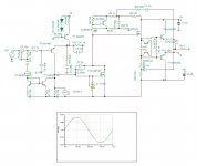
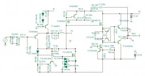
This is first attempt which gave +/- 40v excursion with non sticky saturation. The distortion is 0.0008% at 50W 1khz for now. The IRF540 is assigned arbitrary to be selected for best.
T14/15 do not make part of the circuit, they simulate the function of LM334 1ma.
Attachments
Last edited:
Simplest I found is 25W Class A amp with Lateral MOSFETs.... I will try to design to its best keeping it simplest possible...
There is a model for LM334 posted in LTspice wiki Index of /files/LTspiceIV/examples/LtSpicePlus/Miscel/LM334 Current Source.
Last edited:
Maybe for novice audiophiles to screw your output stage T5-T8 to the JLH1969 instead of the original one? Short-circuit the emitter resistor or by-pass it with a capacitor. Set the quiescent current to 800mA for 10W / 8Ω.
Last edited:
The JLH 1969 is a Classic ,slightly modified by JLH years later because of unobtainable active devices and other slight changes ---acknowledged by practically the whole professional audio engineering community -- at least in the UK .
So forget the "impressive " virtual statistics my question is --
Does it sound better than John,s design ----Musically ??
There must be a large number of design engineers "hanging on at the edge of their seats " for this "revelation" to be revealed ".
So forget the "impressive " virtual statistics my question is --
Does it sound better than John,s design ----Musically ??
There must be a large number of design engineers "hanging on at the edge of their seats " for this "revelation" to be revealed ".
This is not JLH 1969 class A, it is class AB 1970 described here:http://www.keith-snook.info/wireles...orld-1970/15-20W Class AB Audio Amplifier.pdf

Thank you Indra for the LM334.
Thank you Indra for the LM334.
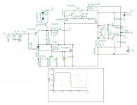
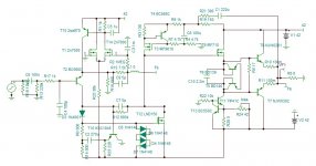
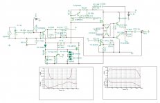
The LM334 functioned perfectly at normal situations but when there is slew rate saturation it goes wrong. The datasheet does speak about its slew rate limitation. So I came up with an innovative solution. I reduce the gate resistor to 1k instead of 10k to have at dc 1.2ma but a bootstrap transistor increase the impedance hence the open loop gain. The IRF540 is replaced by the IRF610 for lower capacitance. The graph shows the square wave of 100khz. The OLBW is 50khz and the distortion is 0.00065% at 50w 1khz. THE NFB is 37db.
Attachments
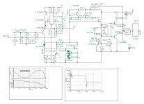
The output can be non-switching but has higher distortion than a standard class ab. I replaced the driver for IRF710 for lower 5th harmonic as now it shows no any sign of crossover. The bias is 160ma the dostortion 50W 1khz 0.0004% with dominant 2nd order and 0.0007% at 10khz.
Probably this is the limit of this topology.
Attachments
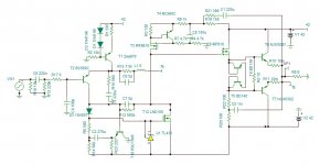
I have nothing against the bootstrap but here the two resistors heat 6.3W. Not admissible on the PCB, so I added a CCS with TIP41C to be on the heatsink and gives the possibility to adjust the bias.
I will review the offset CCS see if I can transform it into DC servo.
Attachments
This amplifier doesn't require any Zobel network. If the capacitive loading is below 400nF it doesn't need any LR. For worst situation with 1uF load and 100uH cable inductance, 0.8uH // 2 ohms is sufficient to have stable operating, see the 10khz square wave.
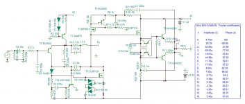
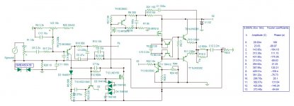
The ground circuit breaker introduces inter-channel link by feedback resistors. For crosstalk cancelation R27/17 must by precise, see the crosstalk Vdb/A.
If you think of any other accessory needed please propose. The current limiting and speaker protection will be dealt in the power supply, however a pair of transistors on board can limit to 6A peak.
Attachments
Last edited:
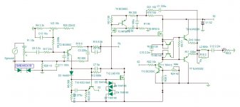
This is with volume control 10k along ground circuit breaker. The generator is simulating the other channel, I could get at best -58db averaged of wiper position. I have never seen a volume control along ground circuit breaker, if someone can show an example?
Note that my input capacitor intended to be 220nF now must be 2.2uF.
Attachments
Last edited:
Any plans for a single supply version, as the original is, for those that require lesser power ?
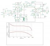
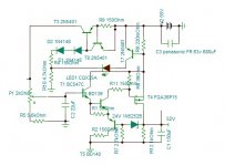
Name the power and I design for you single supply as well as Single Floating Supply (PSU/channel).
This best I can do. 0.005% at 35w 1khz. 0.0008% at 9W.
Attachments
Last edited:
- Home
- Amplifiers
- Solid State
- Audiophile JLH ab