Having used my Audiolab 8000p on the previous night, it now appears to have stopped working on both channels.
When powered up I can hear the transformer hum, yet I do not hear the relays clicks as the once did.
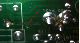
I took the lid off to find one of the track wires which runs from relay RY301 to P422 to have burn't out.
Is it possible that the relays have caused this problem?
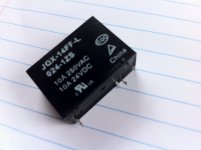
I have jumped the gun a little and ordered 2 x OMRON G2R-1 DC 24V 5PIN in hope this could be the case.
Anyone with any ideas on this?
When powered up I can hear the transformer hum, yet I do not hear the relays clicks as the once did.
I took the lid off to find one of the track wires which runs from relay RY301 to P422 to have burn't out.
Is it possible that the relays have caused this problem?
I have jumped the gun a little and ordered 2 x OMRON G2R-1 DC 24V 5PIN in hope this could be the case.
Anyone with any ideas on this?
Attachments
Have you measured the output transistors to see if any are short circuit. That would be the very first check really. Without seeing the circuit I would guess the relays are probably DC offset protection for the speakers.
You need to check the output transistors for being short circuit as a first step. Also locate that print on the circuit and see what it really connects to and what components it links.
tbh the relays would be the last suspects although if a substantial current has passed or been "broken" by the contacts then they may have suffered. They won't be the cause of the fault though.
is the burnt trace going to the coil or one of the terminals?
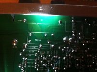
Not sure, here is a pic of the relay's side.
Have you measured the output transistors to see if any are short circuit. That would be the very first check really. Without seeing the circuit I would guess the relays are probably DC offset protection for the speakers.
You need to check the output transistors for being short circuit as a first step. Also locate that print on the circuit and see what it really connects to and what components it links.
tbh the relays would be the last suspects although if a substantial current has passed or been "broken" by the contacts then they may have suffered. They won't be the cause of the fault though.
How would I measure the output of the transistors, and what am I looking for, where about's on the PCB? Sorry, I'm OK with a soldering iron, have a multi meter, just not very electronic minded.
The Audiolab was driving some Jamo THX speakers rather hard the night before. I came in the next day, started checking my levels with test tones, heard one of the Jamo's make a funny noise, then found one of the speakers woofers has fried as a result, also the Audiolab would not output.
Attachments
Last edited:
Have you measured the output transistors to see if any are short circuit. That would be the very first check really. Without seeing the circuit I would guess the relays are probably DC offset protection for the speakers.
You need to check the output transistors for being short circuit as a first step. Also locate that print on the circuit and see what it really connects to and what components it links.
tbh the relays would be the last suspects although if a substantial current has passed or been "broken" by the contacts then they may have suffered. They won't be the cause of the fault though.
I was driving some Jamo THX speakers pretty hard the night before last, when I came home yesterday I checked the levels with a test tone, as soon as I tested one of the Jamo's it made a quiet funny noise then smell, I tested this with a multi meter and found that woofer driver had fried. Output from the Audiolab had also stopped.
Not sure how to test Transistors, any tips? They show no sign of browning.
is the burnt trace going to the coil or one of the terminals?
Not sure, I have posted another pic.
Attachments
![IMG_0619[1].jpg](/community/data/attachments/289/289241-f389a297e97ddbe6a833c7ff04bc93a7.jpg?hash=84mil-l92-)

is the burnt trace going to the coil or one of the terminals?
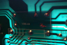
From looking on line I guess the coil is on the 2 pin side, so this must make it the terminal side.
Looking at the relay from the back of the Audiolab's pcb, 2 pins on the left 'coil', then 3 pins on the right. The Right hand channel 3 pins bell differently to the left hand channels?
So it seems the right hand is welded open?
see pic.
Right hand pins 3 & 4 bell out
Left hand pins 4 & 5 bell out
Attachments
Last edited:
If you look down the thread a bit you will see that someone is selling the complete guts for one of these.
http://www.diyaudio.com/forums/swap...0p-amp-transformer-heatsinks.html#post3254102
http://www.diyaudio.com/forums/swap...0p-amp-transformer-heatsinks.html#post3254102
If you look down the thread a bit you will see that someone is selling the complete guts for one of these.
http://www.diyaudio.com/forums/swap...0p-amp-transformer-heatsinks.html#post3254102
Cheers for that.
Think I will have ago at replacing my relays now I have them on order, and take it from there.
If anyone has any other idea's?
I've checked the Transistors, they are all reading between .453/.656V
The relay contacts are changeover or SPDT type. The amplifier output will be connected to either of the 2 grouped terminals. It will be difficult to tell what the relay position is supposed to be if the contacts are welded (and welded means welded together). Remove the relay cover carefully with the aid of of a thin knife point to simply verify that the relay action is free or stuck in one position.
As you have spares on order, the bigger concern is the output stage. i.e. output transistors, driver transistors, associated resistors, rail fuses and power supply fuses. Don't assume all is well there unless the transistors are working in circuit or at working currents. The output transistors are expensive and difficult to come by. Some large service parts distributing companies in the UK and represented elsewhere, seek to make high margins supplying those big Sanken semis.
It is better to find out the bad news now, as Mooly indicated, rather than later when you have wasted time and money on the wrong problem. In any case, the PCB trace is repairable with an appropriate length of enamelled copper wire, so long as it is restrained from movement and causing later woes.
Last edited:
Thanks. Looks like I will have to remove the relays from the PCB to check.
All these things you speaks of, are they generally visible faults, i.e burst caps, or will it come down to testing?
All these things you speaks of, are they generally visible faults, i.e burst caps, or will it come down to testing?
![IMG_0626[1].jpg](/community/data/attachments/289/289492-f35bf483424eef5e0214e832a305e28f.jpg?hash=81v0g0JO71)
Transistors seldom fail with visible signs, perhaps because of brief fault duration. Power resistors, such as those fitted to the emitter of either output transistor, can be ceramic encased and show no sign either but the round, coated types do show visible signs since the wire winding is visible through the thin coating. Small carbon and metal film resistors may show only tiny holes or scorch spots or even be reduced to a charred black stick but you can usually check these by comparing resistance measurements with their counterpart in the other channel. Be sure to do this too, when rechecking your transistor measurements.
I doubt if caps will be a problem yet, as you probably give the amp a regular workout. It may be worth routine replacement of those in the amplifier section, whilst you have it apart and are in the thinking mode. I would be loath to tackle anything that involved resettting the bias, though. That model is a royal PITA to tackle, as outlined in the service manual, available free at Hifiengine.com. and elsewhere.
I doubt if caps will be a problem yet, as you probably give the amp a regular workout. It may be worth routine replacement of those in the amplifier section, whilst you have it apart and are in the thinking mode. I would be loath to tackle anything that involved resettting the bias, though. That model is a royal PITA to tackle, as outlined in the service manual, available free at Hifiengine.com. and elsewhere.
You need to power this up via a bulb tester for faultfinding. If you can't find any obvious shorted output transistors then you must switch on (no speakers attached) and check the DC offset of the amp) which must be near to zero volts DC.
If your prepared to put the work in testing this in methodical fashion then there is a fair chance of repairing it but it has to be done step by step 🙂
It means a fair few basic tests and checks which we can outline in simple steps... up to you 🙂 No guarantees, but if you can solder/unsolder neatly then you are in with a good chance.
Just randomly replacing parts will probably lead to disappointment and frustration.
Whilst you have the relay out, you could flash the output of something with 10-30V DC across the coil terminal to see if it does "click" when power is available. That will also indicate whether it's welded, if the coil still reads continuity with your meter.
I have even used my Laptop PSU for this and many other makeshift purposes! 😉
I have even used my Laptop PSU for this and many other makeshift purposes! 😉
You need to power this up via a bulb tester for faultfinding. If you can't find any obvious shorted output transistors then you must switch on (no speakers attached) and check the DC offset of the amp) which must be near to zero volts DC.
If your prepared to put the work in testing this in methodical fashion then there is a fair chance of repairing it but it has to be done step by step 🙂
It means a fair few basic tests and checks which we can outline in simple steps... up to you 🙂 No guarantees, but if you can solder/unsolder neatly then you are in with a good chance.
Just randomly replacing parts will probably lead to disappointment and frustration.
Thanks Mooly & Ian
I have checked the relays as you said, and the one with the burn't track is not clicking.
Can I still check things or should I wait for a new relay?
How do I test via a bulb tester? Do you mean voltage tester, test lamps?
Last edited:
The bulb tester is a 60 or 100 watt mains filament lamp in series with the live mains to the amp. It limits current in the event of a fault.
Yes you can check things. Basic checks are the output transistors (which you have done and they don't appear to be short... you checked middle leg to the emitter ?) and also the low value emitter resistors (those white stand up ones).
With the amp on there should be around zero volts DC on the speaker output. If the relay isn't closing then you have to measure on the PCB before the relay.
Try that and if you want to proceed further I'll see if I can turn up a circuit and we'll take it from there.
Yep, checked the middle leg.
The low value emitters, c110 & c210 are both sat on .69V, the other 2 c111 & c211 set off around .3V and rise.
Power on, it's showing 0.005 VDC on the R output.
Where about's on the PCB do I measure for the faulty relay, coil side? if so this is readin .09 VDC, checked on the R channel reads 0.0 VDC
I'll come back to you on this... out of time... and I also need to see the circuit to advise properly 🙂
Your relay voltages. Its not the coil voltage your measuring but the voltage "into" the relay switch section. That will come directly from the output stage.
Your relay voltages. Its not the coil voltage your measuring but the voltage "into" the relay switch section. That will come directly from the output stage.
- Status
- Not open for further replies.
- Home
- Amplifiers
- Solid State
- Audiolab 8000p stopped working.