Hi - I'm new to this forum, so please be gentle. 🙂
Audiolab 8000P, with one channel not working. Very loud crackle and pop from the bad channel.
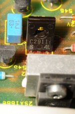
I've looked inside, and see that one transistor (?) SC2911 looks to be toasted - scorched around the solder, and a bit loose on the board. Not good, I think....
I had the same problem a few years ago, possibly on the other channel, and it looks like another one was replace by hi-fi shop technician. Not a pretty job, but did work for a while.
Question:
- is this likely to be a source of the failure?
- if so, where can I buy some replacements (in the UK)? (nikko-electronics.co.uk comes up on google.)
- any other advice?
It's an old box now, so can't justify spending too much on it - also skint 😱
I don't want to just bin it, as it sounds great when it is working.
Thanks
Audiolab 8000P, with one channel not working. Very loud crackle and pop from the bad channel.
I've looked inside, and see that one transistor (?) SC2911 looks to be toasted - scorched around the solder, and a bit loose on the board. Not good, I think....
I had the same problem a few years ago, possibly on the other channel, and it looks like another one was replace by hi-fi shop technician. Not a pretty job, but did work for a while.
Question:
- is this likely to be a source of the failure?
- if so, where can I buy some replacements (in the UK)? (nikko-electronics.co.uk comes up on google.)
- any other advice?
It's an old box now, so can't justify spending too much on it - also skint 😱
I don't want to just bin it, as it sounds great when it is working.
Thanks
Are you sure you have the correct part number, what is the component reference on the PCB ?I've looked inside, and see that one transistor (?) SC2911
Thanks
Usually something takes out a transistor, they tend to be pretty long lived on their own. In a very old home installed box, it is not as likely the speaker wiring was shorted as it would be in a bar band amp. More likely on old amps, the fan stuck, or the electrolytic caps the semiconductor drives got dry and leaky. These are aluminum cans with minus in balls pointing at one lead, or plus pointing to the other. They can also look like peanut M&M's, the tantalum ones. Before replacing the one burned transistor, check the other semiconductors driving it that they aren't shorted or open with the diode test (diodes) or double diode test (BJ transistors) or the "open drain to source with gate shorted to source" test for MOSFET's. Resistors near the blown up parts should be checked, and low voltage rated caps (under the power supply voltage). The low voltage film caps look like rice grains. Then you can buy all the blown up stuff in one order, and purchase all the over 20 year old electrolytic caps at once, instead of letting them blow up things one at a time. Don't forget to buy heat sink grease if you change anything on a heat sink, and possibly a new insulating washer. If the blown transistor is an output transistor, you need to run the amp into a dummy load as you test it to make sure that any faulty DC doesn't blow the speaker. It is also possible a leaky over age non-polar electrolytic cap in the speaker caused too little impedance and blew the O.T. in the first place. If you don't want the pleasure of learning how to do this, then adding all these parts cost up gives you an estimate of whether to do the replacement-20 year re-up, or buy a new amp and give this one away. I use newark a lot, their UK affiate is farnell.com. They have the expected life of electrolytic caps in the selector table, I try to buy e-caps with life over 2000 hours. Some people like doing this repair thing and buy the short life caps from distributors that have the very best price.
I don't worry too much about matching up part numbers on BJT's. I tend to use MJ stuff in the same package with Vce about double the power supply voltage in TO3 and TO220 (tab) and MPS parts in TO92.I do change all the O.T.'s on one side to similar parts if I change one. If your amp has multiple O.T.'s and emitter resistors lower than 0.5 ohm you have to check the matching of the O.T currents after you install them. If mismatched change out the odd one. Pros use a curve tracer for this matching but I use the amp, slower but cheaper. I do have a 2 trace scope, very handy. Idle current (bias) through the E.R's is also important to be checked and adjusted if necessary: 40 ma is kind of an upper bound, 20 is more usual. Once any output DC is gone you can hook up the speakers.
I don't worry too much about matching up part numbers on BJT's. I tend to use MJ stuff in the same package with Vce about double the power supply voltage in TO3 and TO220 (tab) and MPS parts in TO92.I do change all the O.T.'s on one side to similar parts if I change one. If your amp has multiple O.T.'s and emitter resistors lower than 0.5 ohm you have to check the matching of the O.T currents after you install them. If mismatched change out the odd one. Pros use a curve tracer for this matching but I use the amp, slower but cheaper. I do have a 2 trace scope, very handy. Idle current (bias) through the E.R's is also important to be checked and adjusted if necessary: 40 ma is kind of an upper bound, 20 is more usual. Once any output DC is gone you can hook up the speakers.
Last edited:
Thanks for the replies, folks. Indianajo - I'll re-read your comments and pick out the bits I understand 🙂 (I'm not too clued up on electronics.)
In the meantime, here are a few pics of the board. Maybe even a quick visual may give a clue?
In the meantime, here are a few pics of the board. Maybe even a quick visual may give a clue?
Attachments

Last edited:
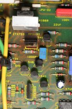
MPSA92 sounds like a legit motorola/on semi number, and ztx753 sounds like a legit diodes inc number. The middle picture looks more like 2sC2911, try that number in datasheetcatalog.com. If they don't have it, maybe NTE has a cross reference. This is probably pretty old, the transistor on the left looks like TO202 package, which is EBC usually. Newer TO220 parts are usually BCE and require twisting the leads around if you are going to use them. In the lower right of the third picture is an electrolytic cap. No visual substitutes for pulling the semiconductors near the blown up one and checking them with the meter tests. The DVM tests don't really prove a transistor good they just prove them bad. I've had double diode okay output transistors blow up later. But, better testers are expensive.
For basics on meter use etc., Electronic Devices, the Electron Flow Version by Thomas Floyd is a useful text I picked up at Goodwill for $2. Retread from the local trade school.
For basics on meter use etc., Electronic Devices, the Electron Flow Version by Thomas Floyd is a useful text I picked up at Goodwill for $2. Retread from the local trade school.
Last edited:

VAS transistors, as here and identified in Jaycee's post above, run with low fixed current in the 6-20mA region, but with high potential, they can still run quite hot. Check how hot in the good channel, with signal and up moderate loud but without speakers. If this one is hot, it might be wise to fit small (tiny) heatsinks to lower the temp and overheating risk that this may well be, considering the repeated failures.
Replace both transistors in the bad channel first, of course, but do check voltages and resistor values, comparing the channels before you do. Sketch it and label voltages on each pin of the Txs, so you know what changes to expect. Fit Txs (the right way) Fit
sinks and go. Recheck voltages and temp. of these in each channel. If different by more than 5%, stop!
Parts... CPC,
CPC - Over 100, 000 products from one of the worlds leading distributors of electronic and related products. | CPC
Transistors so far mentioned all in stock.
The only way you stand a hope of fixing this is to come up with the correct circuit so we can advise and also to power the amp via a "bulb tester" to prevent further damage while working on it.
Thanks again, everyone 🙂
It will take me some time to digest this stuff, but I will certainly look into comparing the 'good' channel vs the 'bad' channel. I think comparing the temperatures, and then (very) basic testing of the 4 individual transistors will be my first line of investigation.
I'll send an update on what I find.
First thing I normally do is look for a schematic. Here's one for this model. Unfortunately this seems to apply to an older version with bipolar input (the amp on the photos has a 2SK389 dual FET) and no 2SC2911 in sight (it does seem to have a '2912 instead), but hopefully it'll give us a general idea of the topology. Looks like it's a beefed-up version of the 8000A integrated amp's circuit. They sure liked their cascodes.
Hmm, resistances at the input are quite imbalanced looking, yet no offset adjustment?!
Hmm, resistances at the input are quite imbalanced looking, yet no offset adjustment?!
Last edited:
Update:
I found the datasheet for the sanyo 2SC2911 transistors to confirm the positions of emitter, collector, base. I then checked the resistance on all combinations with my (pretty basic) multimeter. For the 'bad' side, and Q114 in particular, the readings were
B C E Ohms
- . + 4
- + . high
. - + high
+ . - 4
+ - . 4
. + - high
('.' above just for formatting )
For Q113, Q213, Q214, the readings were ALL high.
I then powered it up for about 20 mins, and then powered it off again.
On the 'good' side, the 1cm square heat sinks on ZTX653, ZTX753 became very hot.
On the ''bad' side, these remained cold.
Similar story for the very large black heatsinks.
No diode test even? That's very basic.
Looks like the transistor may be shorted out B-E.
Q113 should be a BC546, right? No readings at all doesn't sound right either. Anyway, we'll need a diode test mode to say more, anything else is just guesswork right now. Plus it seems the part numbering does not line up with the schematic, so please always state both number and type.
Last edited:
Sorry for the confusion here, but references (as written on the pcb) should be:
Q113, Q213 - 2SA1209S
Q114, Q214 - 2SC2911S
(I'm seeing the benefit of getting a new magnifier ... )
Q113, Q213 - 2SA1209S
Q114, Q214 - 2SC2911S
(I'm seeing the benefit of getting a new magnifier ... )
Why not post a request to see if anyone has a circuit...
and then all things are possible 🙂
Trying to interpret results on an unknown DVM at a distance is asking for trouble beyond obvious open and short conditions. Any good NPN device (or PNP if comparing like with like) will read essentially the same as any other. You must do all tests with them out of circuit too.
I don't do the diode test on my meter, it beeps & burns up the battery and doesn't read numbers. I can't read your language, but all high reading both directions on a Bipolar Junction Transistor in circuit is probably bad. You can get false lows resistance in circuit, but not false opens(1999). Enhancement MOSFet's, open DS is good, with the gate shorted to source. My meter reads 600 ohms on some forward silicon diodes & 450 on others so 4 forwards might be okay, Forwards is the direction the arrow points, like an NPN the plus probe goes on B and the minus to C & E should get 400-600 on both. Output transistors that read 400 instead of 450 forward exploded later, so I like to see the numbers. My meter won't read diodes on 200 ohm scale, not enough voltage at the probes, so I use the 2000 ohm scale. Depends on the type of meter & what battery it uses. Got to have 0.7 volt on the probes to get a reading.
Test the normal readings on your meter on a good silicon diode (non schottky, non zener). Then the transistors should read about the same things, power transistors being a little lower than signal ones.
Test the normal readings on your meter on a good silicon diode (non schottky, non zener). Then the transistors should read about the same things, power transistors being a little lower than signal ones.
Last edited:
A DVM with a diode test usually displays the forward volt drop of the junction... 600 being 600mv etc. So in that sense it's quite useful. A darlington B-E junction should be in the 1.3 region and a germanium junction perhaps as low as 0.12
An AVO with its 15 volt battery for high ohms range beats any DVM for checking leaky junctions.
I have seen many technicians fail to interpret the finer points of checking semiconductors... experience and interpretting the readings is key.
An AVO with its 15 volt battery for high ohms range beats any DVM for checking leaky junctions.
I have seen many technicians fail to interpret the finer points of checking semiconductors... experience and interpretting the readings is key.
update - made some progress here
Hi
I ordered some replacement transistors (2SC2911 and 2SA1209) and replace each of them on the 'bad' side.
And with a bit of trepidation, powered it up using some old cheap speakers.... and the amp is working again. 😀
I may consider replacing the transistors on the 'good' side as well, some time. However, for now, I'm just pleased to listen to it again.
Thanks for all the advice.
( My next challenge is to work out why there is a loud pop/hiss (both speakers) when switching off and on the 8000A (used as a pre-amp). I'll check other posts for this.)
Last edited:
- Status
- Not open for further replies.
- Home
- Amplifiers
- Solid State
- audiolab 8000P - one channel dead - transistor SC2911 looks toasted - (newbie)